


 English
 中文简体
中文简体 русский
Power unit of forward moving stacker
Cat:DC series hydraulic power unit
This hydraulic power unit is specially designed for the forward stacker. It is integrated by a high-pressure gear pump, a DC Carbon brush or brushless...
See DetailsContent
A hydraulic quick coupler that refuses to move is rarely a mechanical fault in the coupler itself. In most cases, residual pressure trapped in the line is pressing the internal poppet against its seat, and the sleeve cannot retract far enough to release the balls or collet. The direct answer to the question "what do I do when a quick coupler will not connect under pressure" is simple: do not force it. Force will not compress the oil, and a standard coupler is not engineered to overcome a column of pressurized fluid. The safe sequence is to vent the trapped pressure, confirm zero pressure at the face, and then connect. For operations where attachments are changed frequently, the more productive answer is to install connect-under-pressure (CUP) couplers or to modify the circuit so that pressure is relieved automatically before the operator reaches for the handle.
On equipment powered by hydraulic power units, such as tail lifts, pallet trucks, lifting columns, dock levelers, and attachment carriers, the quick coupler is the final link in a long chain of components. If the relief valve, the control valve, or the pump circuit is not doing its part, the coupler becomes a daily bottleneck. Understanding where the pressure comes from, what it costs in downtime and component damage, and how to eliminate it at the design stage is the difference between a machine that changes attachments in seconds and one that stops every line changeover. This article covers those causes, the real risks of forced connection, the manual relief procedure, the main connect-under-pressure technologies, and the selection parameters that prevent the problem from returning.
Residual pressure appears in the section of hose between two closed valve surfaces. The classic examples are a cylinder that has been extended and is being held by a check valve, a load that has drifted and settled against a closed poppet, and oil that has expanded because the machine warmed up after shutdown. In all three cases, the oil has nowhere to go until the coupler opens, which is exactly what it cannot do while that pressure is present. The trapped pressure does not leak away by itself; a well-sealed circuit can hold usable pressure for days.
Hydraulic oil expands measurably with temperature. When a machine is parked with an attachment connected and the control valve returns to neutral, the oil between the cylinder port and the coupler is sealed on both sides. As the sun heats the machine or the engine compartment radiates heat, that trapped volume expands. Depending on hose stiffness and the amount of air dissolved in the oil, a 10 °C temperature rise can add tens of bar of pressure at the coupler face. In a completely rigid volume the theoretical rise is higher still; flexible hoses and entrained air absorb part of the expansion, but usually not enough to keep the coupler freely connectable. This is why a machine that connected easily in the morning can be locked solid by mid-afternoon.
A raised platform, a suspended cylinder, or a partially lifted load is held by a pilot-operated check valve or by the porting of the directional valve. The oil under the load is always at pressure, and the check valve prevents it from returning to tank. Internal leakage in the valve spool or in the pump can slowly add to that pressure until the whole branch is pressurized. A double-acting circuit is not automatically immune; the pressurized port is simply the one carrying the load. This is why specifying a DC double-acting power unit with clean porting and tight spool tolerances matters on machines that must disconnect loads frequently.
 DC double acting power unit Manufacturers, Wholesale Factory - Ningbo Panic HydrNingbo Panic Hydraulic Technology Co.,Ltd is China DC double acting power unit manufacturers and OEM/ODM factory, We specialize in wholes...View Product →
Machines equipped with accumulators can hold pressure for hours after the pump stops. The accumulator acts as an energy reserve that continues to push oil into the line even with the engine off. Any coupler in that branch will stay under pressure until the accumulator is properly discharged. The working principle of a hydraulic system makes the risk clear: wherever energy can be stored, it must be released in a controlled way before any connection point is opened. Operators who skip the discharge step are betting against physics, and physics wins.
Forcing a coupler under pressure does not relieve the pressure; it simply moves the failure to the weakest component. The operator may eventually get the coupler partially engaged, but the internal poppet opens only a fraction, and oil escapes at high velocity around the seals. The results range from contaminated faces to serious injury. Every failed attempt also pulls air and dirt into the system, and that contamination then travels through the pump, the valves, and the cylinder, shortening the life of the entire hydraulic power unit.
| Symptom | Mechanism | Typical Result |
|---|---|---|
| Sleeve will not retract | Oil pressure holds poppet against its seat | Scored poppet, bent retainer, coupler replacement |
| Oil spray during the attempt | Partial poppet opening under high differential pressure | Contamination ingression, burns, fluid injection risk |
| Hose whips when the connection finally seats | Sudden release of stored energy | Operator injury, hose damage at the crimp |
| Repeated failed connection attempts | Air drawn past seals on every pull | Aeration, pump cavitation, spongy actuator response |
Fluid injection injury deserves special emphasis. A jet of oil at 100 to 200 bar can pierce the skin and force fluid into tissue without leaving a visible wound. The injury is often mistaken for a minor cut, but it requires immediate medical attention. On top of the human risk, every forced connection increases the maintenance cost of the machine: contaminated oil accelerates valve wear, and a single scored coupler face can leak continuously for the rest of the machine's life.
Manual pressure relief is straightforward when it is done in the correct order. The objective is to give the trapped oil a controlled path back to tank before any coupler is opened. The sequence below applies to machines with single-acting or double-acting circuits and no accumulator. If the machine has an accumulator, discharge it according to the manufacturer's procedure first; the accumulator is the one component that can re-pressurize the line after you believe it is empty.
Manual relief works, but it is time-consuming and depends entirely on operator discipline. For machines that connect and disconnect several times per shift, a better investment is a pressure relief valve located close to the couplers. A correctly set power unit relief valve opens before the coupler is touched, returns the trapped oil to tank, and drops the line pressure to near zero in seconds. The operator never has to crack a fitting, and the risk of contamination entering the system drops dramatically.
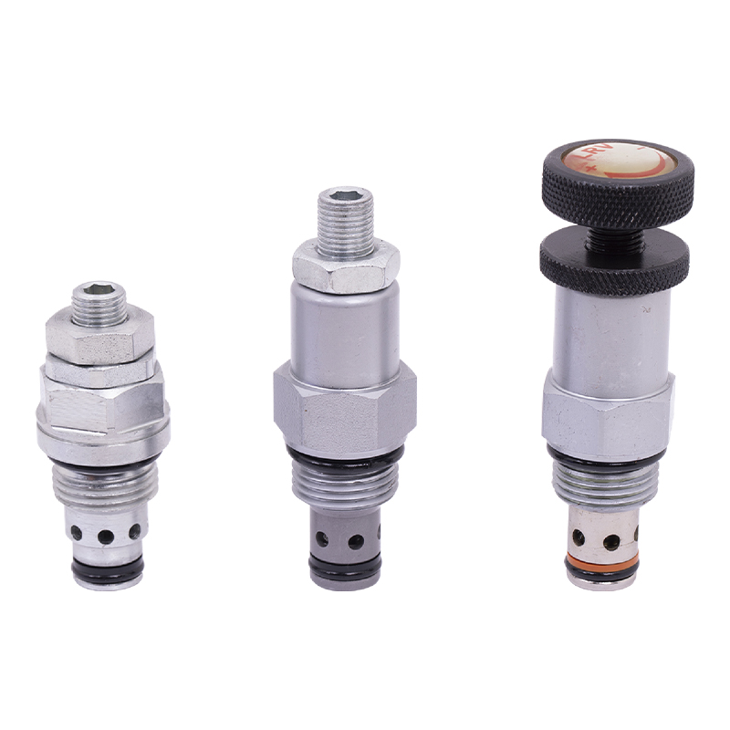 Power Unit Relief Valve Manufacturers, Wholesale Factory - Ningbo Panic HydrauliNingbo Panic Hydraulic Technology Co.,Ltd is China Power Unit Relief Valve manufacturers and OEM/ODM factory, We specialize in wholesale ...View Product →
When the workflow cannot tolerate a manual relief step, the equipment builder can specify couplers that are designed to open while the line is pressurized. These products fall into four families, each with different operating effort, cost, and pressure capability. The boundaries between the families are not always rigid; some couplers combine internal bypass with a threaded collar for the most demanding cases.
This coupler contains a small internal bypass that opens ahead of the main poppet. As the male tip enters, the bypass allows a controlled amount of oil to pass back to the other side, balancing the pressure and letting the poppet open progressively. These couplers handle moderate residual pressure, typically in the range of 10 to 50 bar, without requiring any external valve. They are a practical upgrade for loader and excavator-style attachments where the residual pressure is limited but still enough to jam a standard coupler.
For systems where both the machine side and the attachment side are pressurized, a screw-type coupler gives the operator a mechanical advantage. The threaded collar pulls the two halves together and gradually opens both poppets while oil exchanges between the two chambers. This design allows connection at or near the full working pressure of the system. The trade-off is speed: threading a collar takes longer than a push-to-connect action, so this type is best suited to applications with relatively infrequent changeovers rather than high-frequency tool switching.
When a machine uses four, six, or eight hydraulic lines at once, a multi-coupling plate connects all of them in a single lever movement. The lever multiplies the operator's input force, so the plate can open several poppets simultaneously. These systems are common on quick-change tool carriers, test stands, and large mobile machines where every second of changeover time carries a real cost. The downside is weight and initial cost, which makes this approach worthwhile only when the number of lines is high enough to justify the complexity.
The fourth approach keeps standard couplers and adds a small manifold between the power unit and the coupler set. The manifold contains a manually operated or solenoid-operated vent valve that dumps the cylinder ports to tank before the coupler is opened. This is the preferred solution on machines that must use interchangeable couplers from a specific fleet standard. It also gives the maintenance team a single, familiar service point: if the couplers are hard to connect, the vent valve is tested first, and the couplers themselves are not modified.
Buyers frequently confuse working pressure with the pressure that a coupler can physically survive. Working pressure is the maximum continuous pressure that the coupler is intended to handle during normal operation. Burst pressure is the minimum pressure at which the body or the locking mechanism fails permanently, and it is typically two and a half to four times the working pressure on flat-face couplers. A coupler rated at 250 bar working pressure will usually burst above 700 bar, but that margin exists to protect against fatigue and pressure spikes, not to permit abusive connection attempts.
| Parameter | What to Check | Typical Guidance |
|---|---|---|
| Working pressure | Maximum system pressure at the coupler | Must equal or exceed the relief valve setting of the power unit |
| Burst pressure | Manufacturer's minimum guaranteed failure pressure | Select 2.5 times working pressure or higher |
| Flow capacity | Pressure drop at the rated flow of the pump | Keep pressure drop below 5 bar to limit heat generation |
| CUP capability | Maximum pressure allowed at connection | Match to the worst-case residual pressure after shutdown |
| Frequency of use | Expected connections per shift | Above 20 per shift, specify CUP couplers or a vent manifold |
Pressure drop is the second selection criterion that affects system efficiency. Every coupler adds a flow restriction, and in a high-flow circuit that restriction converts directly into heat. A small flat-face coupler at a high flow rate can drop several bar and raise the oil temperature well beyond the design point of the reservoir. The correct approach is to size the coupler for the pump's maximum flow, not the average flow, and to verify the manufacturer's pressure drop curve. The upstream side of the circuit matters just as much; for fixed installations, the AC hydraulic power unit buyers guide explains how system flow and pressure are determined in the first place.
The fastest way to reduce coupler problems is to design the pressure out of the circuit before the coupler ever sees it. Most residual pressure comes from the directional valve and the relief path. If the valve's neutral position returns both cylinder ports to tank, the trapped oil drains, and the coupler is almost always at zero pressure when the operator arrives. This is standard on well-designed mobile circuits, but it is not universal; some valves use a closed-center neutral that intentionally blocks the ports. The valve type must be matched to the application, not chosen by habit.
Two components control the behavior at the coupler face. The first is the relief valve. A relief valve set 10 to 15 percent above the maximum working pressure provides the safety margin the circuit needs while also protecting the coupler from pressure spikes when the valve closes. The second is the directional control valve. On machines with remote or automatic actuation, a hydraulic solenoid valve with an open-center neutral drains both work ports to tank when de-energized, which is exactly the behavior that keeps a quick coupler free between cycles. Choosing a valve with the correct spool position is as important as choosing the correct coupler rating.
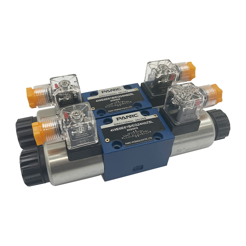 Solenoid Valve Manufacturers, Plug-In Solenoid Valve FactoryNingbo Panic Hydraulic Technology Co.,Ltd is China OEM/ODM solenoid valve manufacturers and plug-in solenoid valve factory, We specialize...View Product →
On the power unit side, a double-acting design gives the operator a positive way to release a suspended load. Instead of relying on gravity to return the oil, the pump pushes oil back through the return line, forcing trapped pressure back across the relief valve. This is why the DC hydraulic power unit selection guide recommends confirming the neutral position of the valve and the relief setting before specifying a machine that will use quick couplers. A properly matched power unit package, including the valve group and tank sizing, eliminates most connect-under-pressure complaints at the source.
Couplers fail gradually. When the sleeve becomes stiff or the poppet leaks internally, operators compensate by pushing harder, and the damage accelerates. A simple checklist aligned with the power unit's service schedule catches most problems before they shut down a job. The list below is deliberately short so that it can be repeated on every maintenance visit without becoming a burden.
One additional test is worth adding to the quarterly schedule. With the machine running and a pressure gauge in the line, record the pressure reading at the coupler immediately after the control valve returns to neutral, and again five minutes later. A reading that climbs over time points to internal leakage or thermal expansion; a reading that stays high points to trapped load pressure. Both conditions can be corrected before they result in a stuck coupler at the worst possible moment.
The questions below cover the most common calls and engineering discussions around couplers, residual pressure, and power unit integration.
Only if the coupler is specifically rated for connect-under-pressure operation and the residual pressure is within its rated limit. Standard flat-face and ball-lock couplers are not designed for this, and forcing them will damage the poppet, the sleeve, or both.
There is no universal threshold because coupler designs differ, but in practice pressures above roughly 10 to 20 bar start to make the sleeve difficult to move. At 50 bar, a standard coupler is usually impossible to connect by hand.
Working pressure is the maximum continuous pressure the coupler is built to handle in normal service. Burst pressure is the minimum pressure at which the body fails permanently. The ratio between the two is the design safety factor, commonly between 2.5:1 and 4:1 for flat-face couplers.
No. The flat-face poppet design reduces spillage and contamination on disconnect, but it does nothing to release the pressure trapped in the line. A flat-face coupler with CUP capability or an external vent valve is required.
Yes. A small relief valve or a vent manifold installed between the power unit and the couplers can drain trapped oil to tank before connection. This is often the most economical upgrade for machines that already use standard interchangeable couplers.
Usually because the two branches have different pressure levels. The branch connected to the rod side of a cylinder may be at atmospheric pressure while the bore side carries the load. Many machines connect freely on the return side and struggle only on the pressurized side.
It can, because the internal bypass adds restrictions and moving parts. A coupler with CUP capability may have a slightly smaller flow path than the same size without CUP. Check the pressure drop curve rather than assuming equal performance.
For machines that connect attachments several times per day, inspect seals at every 500 operating hours and replace them at the first sign of drips. For lighter duty, annual replacement is a reasonable preventive practice, though the actual interval depends on fluid temperature and contamination level.

This hydraulic power unit is specially designed for the forward stacker. It is integrated by a high-pressure gear pump, a DC Carbon brush or brushless...
See Details
This hydraulic power unit is specially designed for dump trailers. It is integrated by a high-pressure gear pump, DC carbon brush machine, central val...
See Details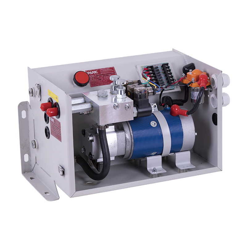
This hydraulic power unit is specially designed for the hydraulic tail plate. The vehicle tail plate hydraulic power unit is a power unit used for the...
See Details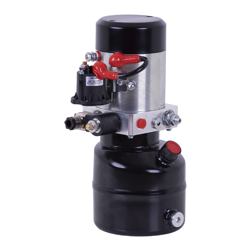
This hydraulic power unit is specially designed for a mobile hydraulic lifting table, which is integrated with a high-pressure gear pump. permanent ma...
See Details
This DC bidirectional pump power unit adopts an integrated design of multiple components such as a bidirectional gear pump, a permanent magnet DC moto...
See Details
The hydraulic power unit is specially designed for the integrated shallow buried hydraulic lifting column, It integrates a bidirectional gear pump, AC...
See Details
This hydraulic power unit is specially designed for hydraulic cargo elevators and is integrated with a high-pressure vane pump, AC Oil immersion motor...
See Details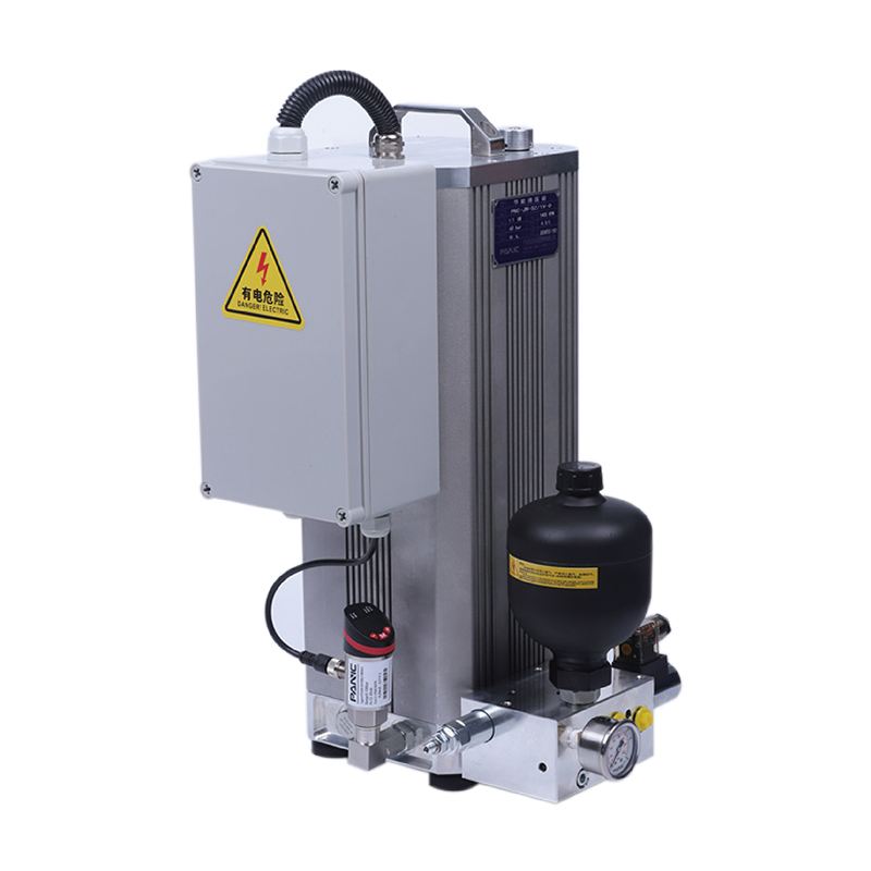
The energy-saving hydraulic station utilizes the working principle of an accumulator, combined with pressure sensors and low-leakage hydraulic compone...
See Details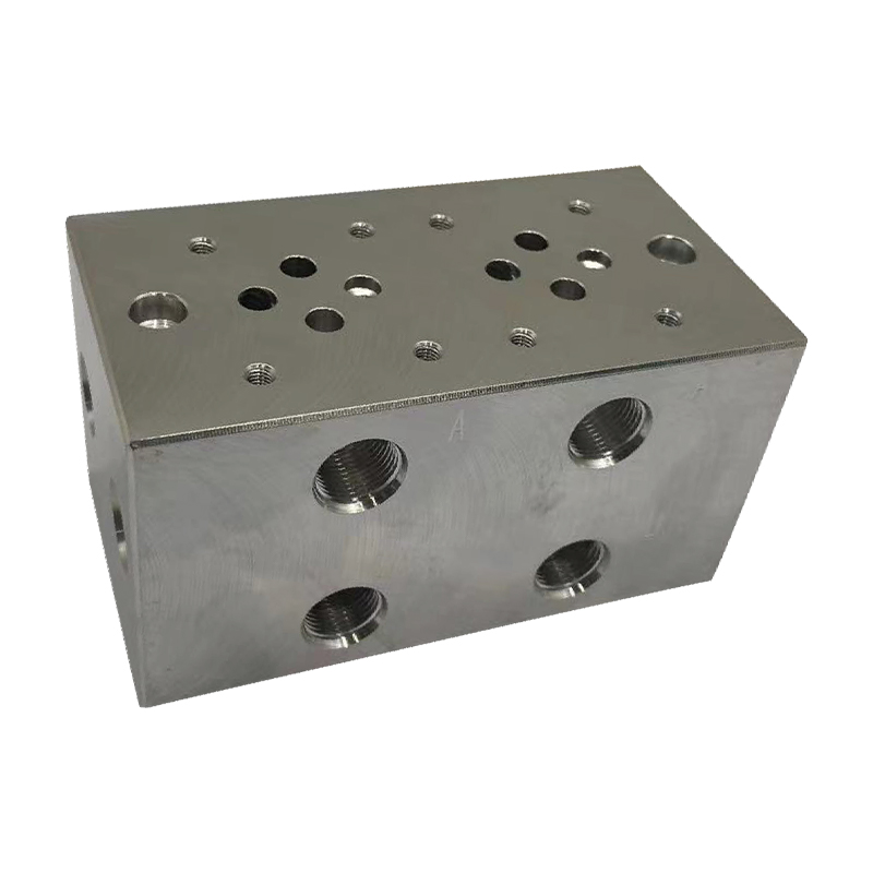
The multi-connection hydraulic integrated valve block is an efficient integrated component of the hydraulic system, including two-connection, three-co...
See Details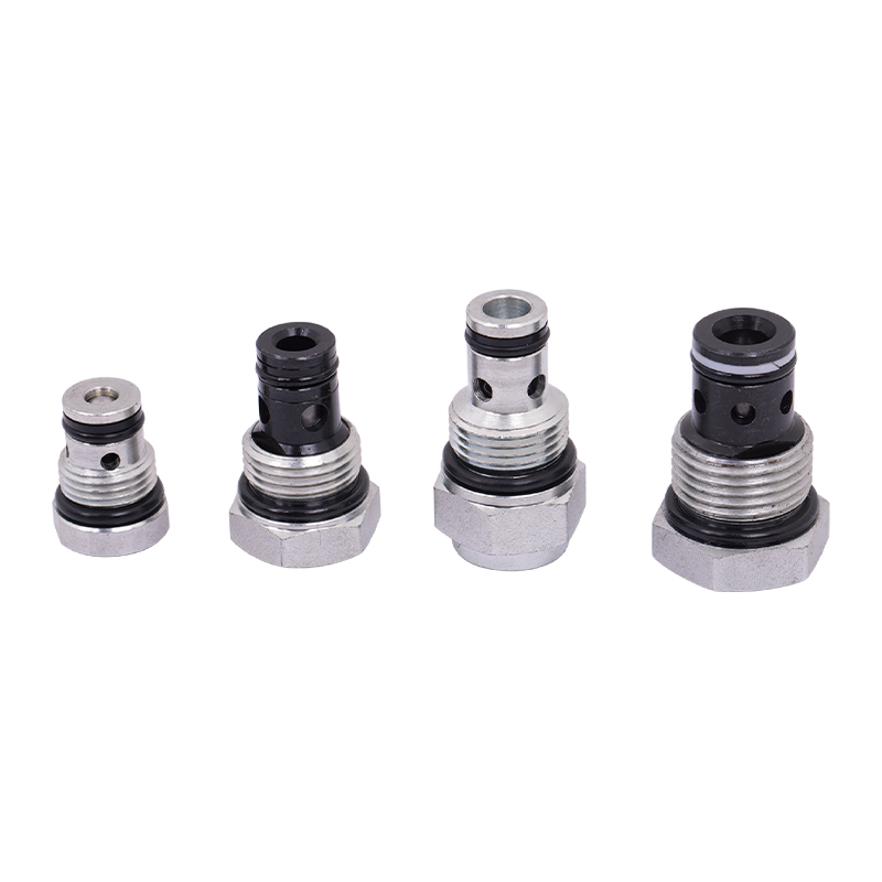
The power unit check valve (also called non-return valve) is a key component for controlling the one-way flow of fluids. It can prevent hydraulic oil,...
See Details
No. 12 Tongji Road, Simen Town, Yuyao City

+86-0574-62130352
+86-18905846028

+86-0574-62130353

Copyright© Ningbo Panic Hydraulic Technology Co., Ltd. All Rights Reserved. China Hydraulic Power Units Manufacturers

