


 English
 中文简体
中文简体 русский
Dump trailer power unit
Cat:DC series hydraulic power unit
This hydraulic power unit is specially designed for dump trailers. It is integrated by a high-pressure gear pump, DC carbon brush machine, central val...
See DetailsContent
The correct answer to “how big should my valve actuator be?” is simple: the actuator must deliver more torque than the valve asks for, at the worst point of the stroke, at the lowest supply condition you can guarantee. Every good sizing method is just a structured way to prove that one condition. The standard industrial starting point is a minimum torque safety margin of 25% above the valve manufacturer’s published maximum break torque.
An actuator that is sized too small will stall before the valve reaches its end stop, leave the valve only partially open or closed, draw excessive current, and eventually fail from overheating or continuous stall. An actuator that is sized too large can be just as damaging: it slams the valve into its seats, bends stems, overstresses the trim, and makes precise control difficult. Sizing is therefore not about choosing the biggest actuator you can find. It is about proving that the low point of the actuator curve sits above the high point of the valve torque curve.
Bottom line: under-sizing causes failure to operate, while reckless oversizing causes mechanical damage. A documented torque calculation protects both the valve and the actuator, and it gives the project team a record they can recheck when process conditions change.
Sizing starts with torque data from the valve manufacturer. For a quarter-turn valve you need four values: break torque, running torque, end torque, and the maximum shut-off torque at your design differential pressure. For a linear valve you need the equivalent thrust values. Without this data sheet, any actuator selection is guesswork.
| Torque component | When it matters | What drives it |
|---|---|---|
| Break torque | Start of stroke | Seat interference, differential pressure, hardened or aged seat material |
| Running torque | Mid-stroke | Packing friction, bearing friction, flow-induced torque |
| End torque | End stops | Seat compression, travel stops, pressure loading in closed position |
Use this procedure for both new valves and retrofit projects. It works for pneumatic, hydraulic, and electric actuators, with only the torque-supply calculation changing between the technologies.
This sequence looks simple, but the verification step is where most sizing errors survive. Always run the four-point torque check before you approve a spring-return actuator for purchase.
The safety factor is the simplest and most misunderstood part of actuator sizing. It is not permission to pick a random larger model. It is a deliberate allowance for the uncertainties that appear in every real installation: torque measurement tolerance, packing aging, seat wear, off-design differential pressure, and dirty process media. Each of these increases the torque the valve actually demands compared with the fresh-valve data sheet.
| Service condition | Typical margin | Reason for the margin |
|---|---|---|
| Clean water, air, general services | 1.25 | Clean media, low wear, stable packing friction |
| Process fluids with deposits or solids | 1.5 | Deposits on stem and seat increase break torque over time |
| Safety isolation, fire and gas duties | 1.5 to 2.0 | The valve must close even with corroded parts and degraded packing |
| High cycle count or fast stroking | 1.5 | Wear raises torque steadily over thousands of cycles |
Write the chosen safety factor into the technical specification so that the next engineer, or the valve package vendor, can reproduce your calculation exactly. A margin that is not documented will be renegotiated at every project meeting, and the result is often an unnecessarily large actuator bought to settle an argument.
A spring-return actuator produces a different torque at every position because the spring compresses as the actuator strokes. The air torque is highest when the actuator first starts to move and lowest when the spring is fully compressed. The spring torque is the opposite: lowest at the open position, highest at the closed position. That is why a single torque number is never enough for a fail-safe actuator.
For a fail-closed spring-return actuator, verify these four operating points in order:
A common failure is checking only the spring end torque. In many scotch-yoke designs, the air torque drops by 30% to 50% between the open and closed positions. If the air end torque falls below the running torque, the valve will creep toward the closed position during normal operation, and the positioner will fight the actuator all day.
The following calculation uses illustrative values. Replace them with the torque data from your specific valve manufacturer before making a purchase decision.
A process plant needs to automate a 6-inch (DN150) resilient-seated butterfly valve for water isolation. The valve manufacturer specifies a break torque of 200 N·m, a running torque of 110 N·m, and an end torque of 90 N·m at a 10 bar shut-off differential pressure. Available pneumatic supply is 5.5 bar. The valve must fail closed on loss of air.
| Verification point | Required torque | Actuator output | Result |
|---|---|---|---|
| Air start (opening) | 200 (break) | 380 | Pass |
| Air end (fully open) | 110 (running) | 300 | Pass |
| Spring start (closing) | 110 (running) | 160 | Pass |
| Spring end (closed) | 200 (seating) | 275 | Pass |
Now check the same actuator at a degraded supply pressure of 4 bar. The pneumatic output scales linearly with pressure: air start becomes 380 × 4 ÷ 5.5 = 276 N·m, and air end becomes 218 N·m. The spring values do not change. The opening margin shrinks from 180 N·m to 76 N·m, but the configuration still passes. This is the correct way to use a pressure check: always verify at the minimum supply you can guarantee, not at the nominal plant pressure.
Electric and pneumatic actuators get most of the attention in generic sizing guides, but hydraulic actuators offer the best power density of the three technologies. Because a hydraulic system typically runs at 70 to 210 bar, instead of 3 to 8 bar for plant air, a compact hydraulic cylinder can produce the torque that would require a much larger pneumatic actuator.
Two differences matter when you size a hydraulic actuator. First, the maximum output is set by the relief valve setting, not by the pump’s maximum pressure rating. Second, the actuator torque is calculated from the effective piston area and the differential pressure across the piston at the moment of operation. Work backwards: choose the relief valve setting first because it defines the torque ceiling, then size the flow path for the required stroke time, then confirm the pump and motor can deliver the flow.
The control loop is where most hydraulic sizing problems appear. In a standard valve-actuator package, a hydraulic solenoid valve switches flow direction to extend and retract the actuator. A power unit regulating valve trims the flow rate so that the stroke time stays inside the process limit. A power unit relief valve protects the valve seat from torque spikes by limiting the maximum system pressure.
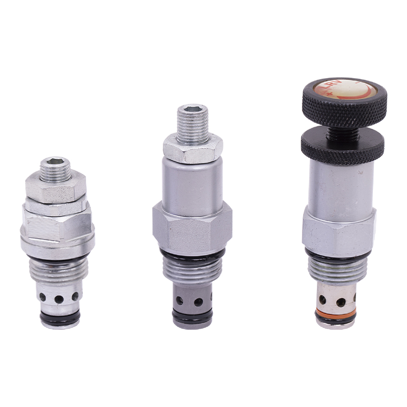 Power Unit Relief Valve Manufacturers, Wholesale Factory - Ningbo Panic HydrauliNingbo Panic Hydraulic Technology Co.,Ltd is China Power Unit Relief Valve manufacturers and OEM/ODM factory, We specialize in wholesale ...View Product →
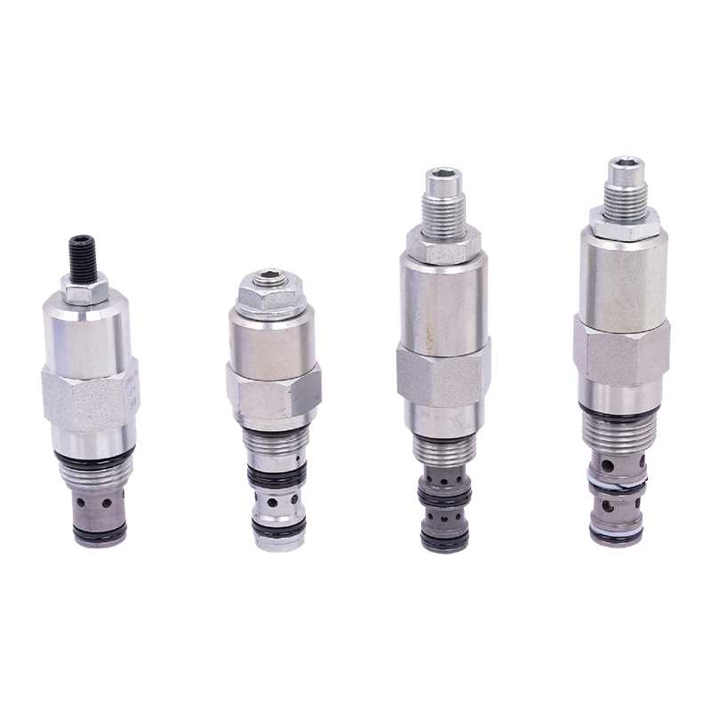 Power Unit Regulating Valve Manufacturers, Wholesale Factory - Ningbo Panic HydrNingbo Panic Hydraulic Technology Co.,Ltd is China Power Unit Regulating Valve manufacturers and OEM/ODM factory, We specialize in wholes...View Product →
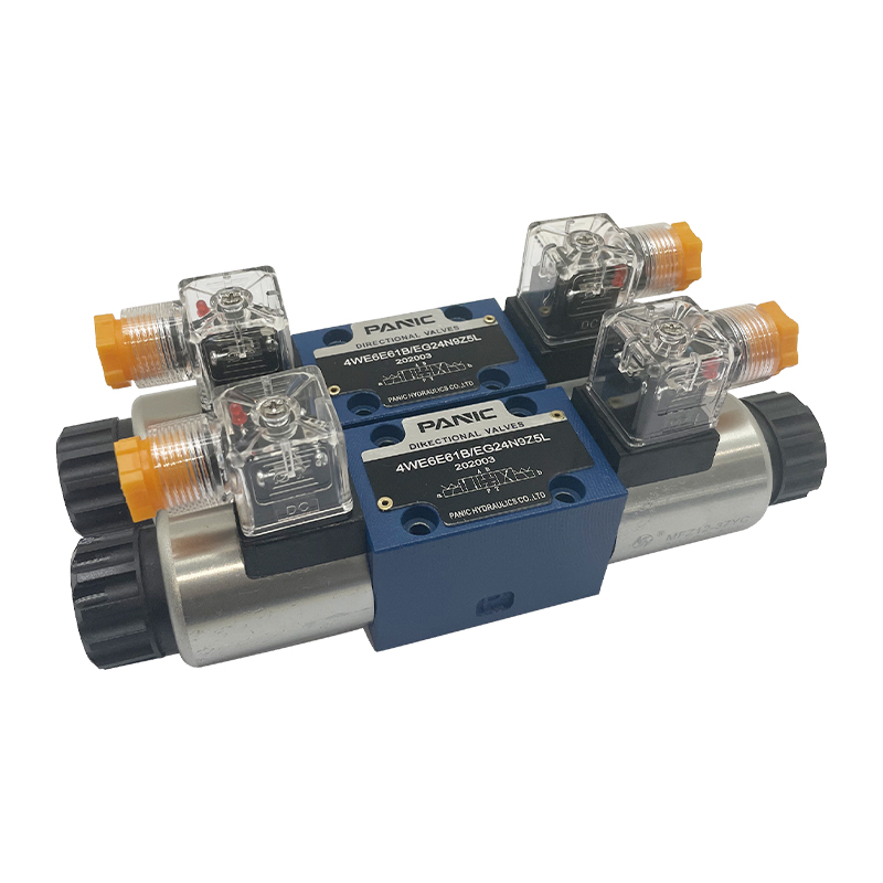 Solenoid Valve Manufacturers, Plug-In Solenoid Valve FactoryNingbo Panic Hydraulic Technology Co.,Ltd is China OEM/ODM solenoid valve manufacturers and plug-in solenoid valve factory, We specialize...View Product →
The sizing sequence for a hydraulic actuator package is straightforward. Calculate the required torque from the valve data sheet and safety factor. Convert torque to a required pressure differential using the actuator’s effective area and moment arm. Set the relief valve at a value comfortably above that pressure, usually 10% to 20% higher, so the actuator can develop full torque without the relief valve lifting. Then size the pump and motor so the flow is enough to stroke the valve within the required time. Finally, confirm that the solenoid valve has a large enough flow coefficient, and let the regulating valve fine-tune the stroking speed.
All of this assumes you understand the working principle of a hydraulic system, especially how pump flow, valve response, and actuator displacement interact during a fast stroke. In practice, hydraulic power units are relatively easy to operate compared with mechanical power units, which is why hydraulic valve actuation is common on large-bore isolation valves, tank farm gates, and heavy lifting equipment.
Most actuator failures are not caused by a defective product. They are caused by an incomplete calculation at the engineering stage. These seven mistakes appear again and again in field reports and commissioning records.
Before you finalize a purchase order, run through this checklist with the valve data sheet and the actuator catalog in front of you. A negative answer on any item means the sizing is not complete.
If you are building a hydraulic power unit to drive the actuator, review our AC hydraulic power unit buyer’s guide before you commit to a pump and motor size. The torque requirement from the actuator becomes the pressure and flow requirement that the power unit must deliver.
The 25% rule means the actuator output torque must be at least 1.25 times the valve’s maximum published break torque. It covers measurement uncertainty, aging packing, and minor differences between the tested valve and the delivered valve. Treat it as a floor, not as a target. Increase it to 1.5 or higher when the process is dirty, abrasive, or safety-critical.
Because the torque output changes with position. Air torque is highest at the start of the stroke and lowest when the spring is fully compressed; spring torque is the reverse. A single catalog value cannot tell you whether the valve will open fully, close fully, and hold position through the whole stroke. Only the air start, air end, spring start, and spring end values can do that.
Yes. A margin above roughly 2 times the required break torque can compress the seat beyond its design range, bend the stem in side-loaded designs, produce water hammer during fast closure, and make control-loop tuning very difficult. The goal is a proven positive margin, not the largest actuator in the catalog.
For pneumatic actuators, output torque scales almost linearly with supply pressure. An actuator producing 380 N·m at 5.5 bar delivers only 276 N·m at 4 bar. For hydraulic actuators, torque scales with the differential pressure across the piston, which is capped by the relief valve setting. Always size at the minimum pressure the system can sustain.
Ask for the break torque, running torque, and end torque at the maximum differential pressure and maximum temperature, for both flow directions. For linear valves, request seat load, packing friction, and the unbalanced area. Also ask whether the published values already include a safety margin, so you do not add a second margin on top.
Choose hydraulic actuation when the required torque is very high, when installation space is tight, when plant air is unreliable or poorly dried, or when you need a consistent force independent of air supply fluctuations. Hydraulic systems are also a strong fit for large-bore isolation valves, hoists, and mobile equipment where a hydraulic power source already exists.
Valve actuator sizing is a verification loop, not a single table lookup. Re-run it whenever the valve size, pressure class, process medium, or supply pressure changes. Document every input — break torque value, safety factor, spring-end torque, and the minimum supply pressure that you actually guarantee — and keep that file together with the valve data sheet.
The actuator that passes all four torque checks at minimum supply, meets the required stroke time, fits the standard mounting flange, and leaves a documented margin is the correct one. That is the whole job — done properly, it prevents the most expensive failure mode in any valve system: the one that appears only after the actuator is bolted on and the process is running.

This hydraulic power unit is specially designed for dump trailers. It is integrated by a high-pressure gear pump, DC carbon brush machine, central val...
See Details
This DC micro power unit combines high-pressure gear pumps, DC motors, center valve blocks, cartridge valves and oil tanks. It is compact and powerful...
See Details
This hydraulic power unit is controlled by a brushless motor and can be divided into external and internal drives based on power. It is integrating co...
See Details
This boarding axle power unit is specially designed for fixed boarding ramps and integrates a high-pressure gear pump, an AC motor center valve block,...
See Details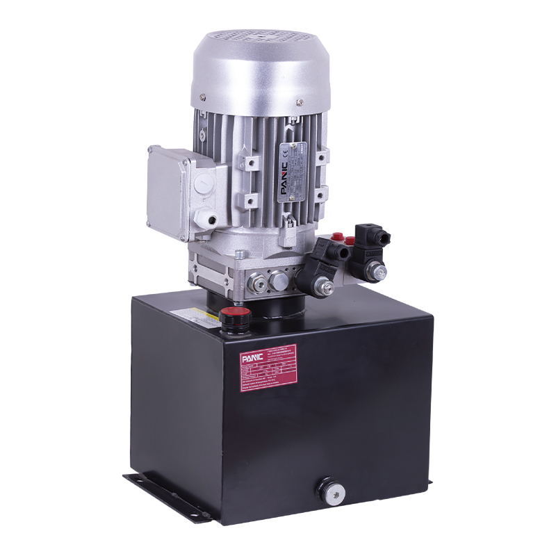
This hydraulic power unit is designed for scissor lifts and integrates a high-pressure gear pump, AC motor, center valve block, cartridge valve and oi...
See Details
This hydraulic power unit is specially designed for the clamping cylinder of the machine, too. It is integrated by a high-pressure gear pump.AC motor,...
See Details
The hydraulic power unit is specially designed for the integrated shallow buried hydraulic lifting column, It integrates a bidirectional gear pump, AC...
See Details
This hydraulic power unit is specially designed for hydraulic cargo elevators and is integrated with a high-pressure vane pump, AC Oil immersion motor...
See Details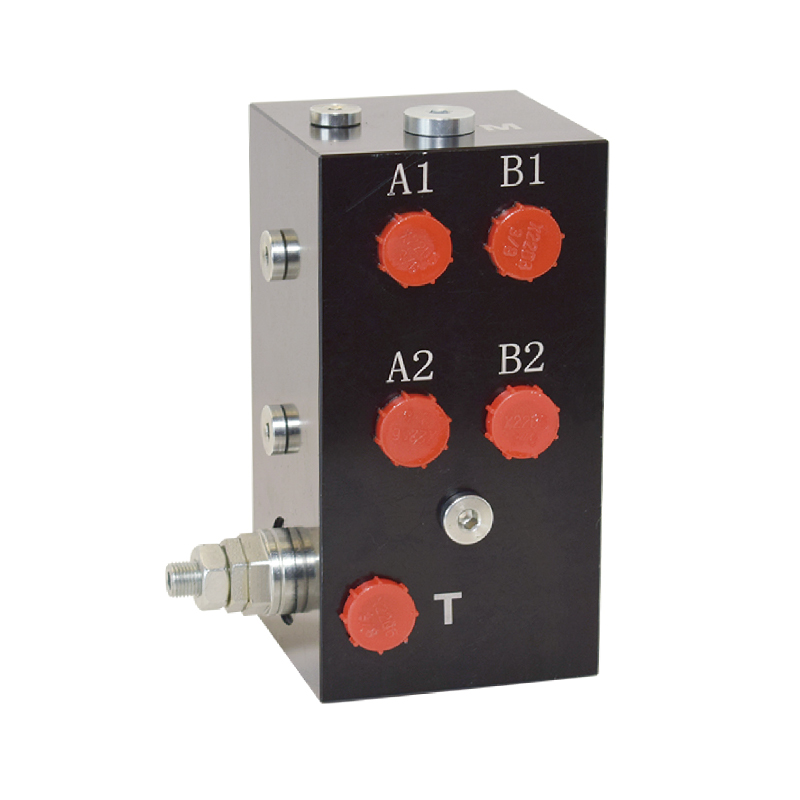
The hydraulic valve block centrally installs various hydraulic valves through the internal precision flow channel, solves the problems of bloated and ...
See Details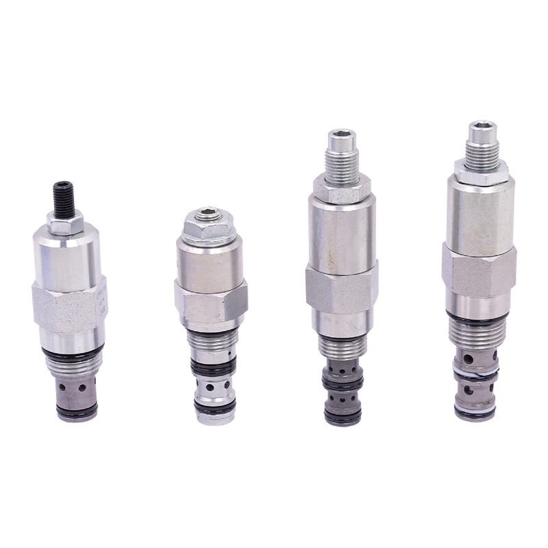
The regulating valve is a key device used in industrial control systems to adjust parameters such as fluid flow, pressure, and temperature. It can acc...
See Details
No. 12 Tongji Road, Simen Town, Yuyao City

+86-0574-62130352
+86-18905846028

+86-0574-62130353

Copyright© Ningbo Panic Hydraulic Technology Co., Ltd. All Rights Reserved. China Hydraulic Power Units Manufacturers

