


 English
 中文简体
中文简体 русский
Mini Pallet Truck Hydraulic Power Unit
Cat:DC series hydraulic power unit
This hydraulic power unit is specially designed for all electric pallet truck.It consists of high voltage gear pump,permanent magnet DC motor and cent...
See DetailsContent
Hydraulic systems design is the disciplined process of converting prime mover energy into precisely controlled mechanical motion through pressurized fluid. The direct conclusion up front: a reliable hydraulic system is built on four decisions made in order — set the working pressure, size the flow, choose the circuit architecture, and select components with verified ratings. When engineers skip that sequence and jump straight to component selection, the typical consequences are overheating, sluggish actuator motion, pump cavitation, and costly field retrofits. This guide consolidates the design workflow, sizing methods, efficiency levers, and common mistakes, supported by tables you can use as a reference during an actual design review.
Every hydraulic system obeys the same physical laws. Pressure creates force, flow creates speed, and the product of the two defines hydraulic power. The designer's job is to deliver that power to the actuator with acceptable losses and predictable behavior across the full operating envelope.
The working pressure is the first parameter to fix because it drives the size of every other component. Industrial machinery commonly runs between 100 bar and 210 bar, while mobile equipment, where weight matters, typically operates at 250 bar or higher. A higher pressure ceiling allows smaller cylinders and smaller reservoirs, but it also raises internal leakage, heat generation, and the cost of hoses, fittings, and seals.
Flow rate determines actuator velocity and directly sets the displacement of the pump. A 50 mm bore cylinder that must extend 400 mm in 4 seconds needs 11.8 L/min of flow before accounting for leakage. Pressure drop across valves and fittings scales with the square of flow velocity, so pipe and hose diameters must be selected to keep fluid velocity below 4.5 m/s on the pressure side and under 1.5 m/s on the return side.
Safety margins used in professional design reviews:
Before selecting individual components, the engineer must define the circuit topology. The most common architecture is the open loop circuit, where fluid is drawn from the reservoir, delivered to the actuator through a directional valve, and returned to the reservoir after doing work. Open loop circuits dominate fixed industrial equipment because they are simple, tolerant of contamination, and easy to troubleshoot.
Closed loop systems circulate fluid directly between the pump and motor, with only a small charge pump replacing leakage. These circuits deliver higher efficiency on continuous rotary motion applications such as winch drives and track drives, but they require more precise filtration and a deeper understanding of loop stability. For most linear-motion machines like presses, lifts, and clamps, an open loop with a well-designed valve manifold is the right choice.
Load holding is a separate design decision that must never be an afterthought. Vertical loads need counterbalance valves, pilot-operated check valves, or mechanical locks to prevent drift. The classic failure mode is a horizontal cylinder drifting under gravity when the directional valve spool leaks internally. Counterbalance valves with a pilot ratio of 3:1 to 8:1 are a standard solution, and their cracking pressure must be set at least 30% above the load-induced back pressure.
Accumulators are also part of circuit architecture. A bladder or piston accumulator can store energy for peak motion demands, reduce pump size, damp pressure spikes, or act as an emergency lowering source. For applications with a short high-flow peak followed by a long idle period, an accumulator circuit can cut pump flow requirements by up to 60%, with direct savings on motor power and heat generation.
A full treatment of the physics behind these circuits appears in our explanation of the working principle of a hydraulic system. When the circuit design is settled, many manufacturers prefer to procure the pumping, valving, and reservoir as one preassembled unit. A custom hydraulic station that matches the circuit diagram eliminates the risk of mismatched port sizes and simplifies installation on the machine builder's side.
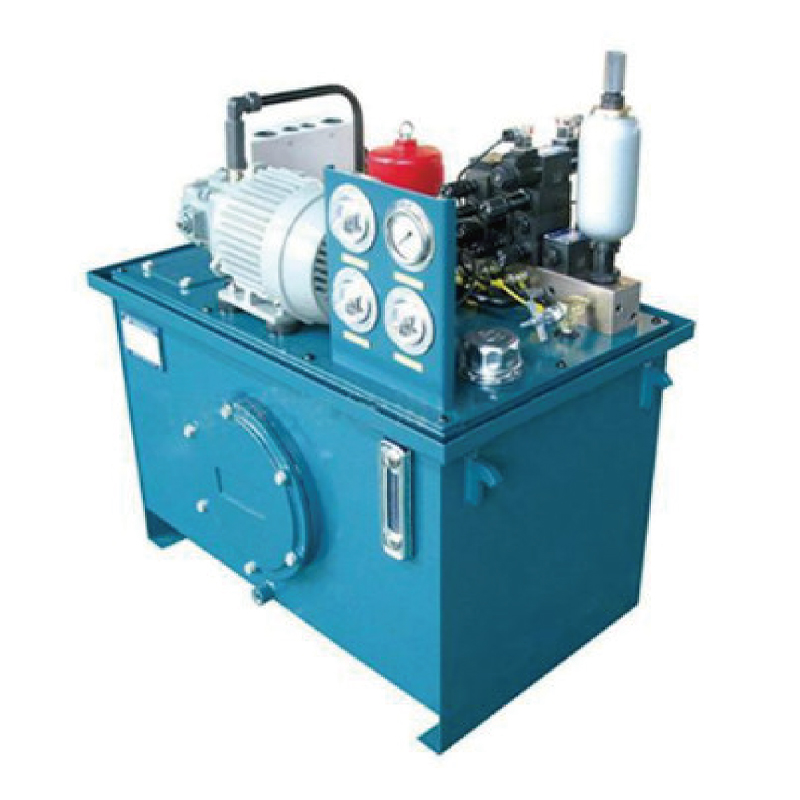 Wholesale Hydraulic Pump Station Manufacturers, OEM/ODM FactoryNingbo Panic Hydraulic Technology Co.,Ltd is China OEM/ODM Hydraulic pump station manufacturers and hydraulic pump station factory, We sp...View Product →
The fastest way to understand hydraulic sizing is to work through a concrete example. Consider a lifting platform that must raise a 3,000 kg load through 200 mm of stroke in 6 seconds. The design pressure is set at 160 bar.
Step 1 — Calculate the force requirement. The gravitational force is 3,000 kg multiplied by 9.81 m/s², which equals 29.43 kN. Add a 10% friction allowance, giving 32.4 kN as the required piston force.
Step 2 — Select the cylinder bore. The piston area is force divided by pressure: 32,400 N divided by 16 MPa equals 2,025 mm². This corresponds to a bore diameter of 50.8 mm, so the next standard bore size is 50 mm. Checking the selection, a 50 mm bore at 160 bar delivers 31.4 kN, which is marginally lower than the friction-inclusive estimate; stepping up to 63 mm provides 49.9 kN, which is the safer choice for a production lift.
Step 3 — Determine the required flow rate. The stroke of 200 mm in 6 seconds gives a piston velocity of 33.3 mm/s. With a 63 mm bore, the piston area is 3,117 mm², so the flow is 6.23 L/min. Adding a 15% leakage margin yields a design flow of 7.2 L/min.
Step 4 — Size the pump and drive motor. At 1,450 rpm, a gear pump displacement of 5.0 cc/rev delivers 7.25 L/min. The hydraulic power equals pressure multiplied by flow divided by 600: 160 bar x 7.2 L/min / 600 = 1.92 kW. Assuming 85% pump efficiency, the installed motor must provide at least 2.26 kW, so a 2.2 kW motor is the minimum, with 3 kW as a more robust choice if the duty cycle is continuous.
For designers who want to skip repeated sizing calculations on similar machines, using a pre-engineered lifting platform power unit saves time and reduces procurement risk. These units already match pump, motor, tank, and valve group to the duty class of the application, with only the cylinder and connecting hoses left to specify.
 Wholesale Lifting Platform Power Unit Manufacturers, FactoryNingbo Panic Hydraulic Technology Co.,Ltd is China OEM/ODM lifting platform power unit manufacturers and factory, We specialize in wholes...View Product →
Hydraulic systems convert mechanical energy into hydraulic energy and then back into mechanical motion. Every conversion stage loses some energy to heat. A typical fixed-displacement gear pump system with proportional valves has an overall efficiency of 55 to 75%, meaning 25 to 45% of the input power becomes heat. If a machine draws 10 kW and the system efficiency is 65%, the heat load reaches 3.5 kW, enough to raise a 100 L tank by 50°C in under two hours without a cooler.
The most effective efficiency measures, ranked by impact: variable-displacement pumps that reduce flow during standby; load-sensing controls that match pressure to the load; accumulator circuits that shift stored energy to peak phases; and low-pressure-drop valves with larger spool bores.
Heat exchanger sizing follows a simple rule. Once the heat load in kilowatts is known, divide it by the allowable temperature rise above ambient, multiplied by the heat transfer coefficient of the cooler type. For example, a 3 kW heat load with a 30°C rise and a coefficient of 0.025 kW/°C·m² requires 4 m² of effective cooling area. Most commercial air-cooled heat exchangers list their dissipation capacity at a standard temperature difference, so the selection is a direct lookup once the heat load is fixed.
For machines that operate intermittently with long pauses, a correctly sized reservoir with aluminum-plate cooling ribs often eliminates the need for an oil cooler. In continuous-duty applications such as presses or conveyor drives, a thermostatic bypass from the relief valve back to the tank is a simple but effective way to keep oil temperature in the optimal 40 to 55°C window.
Hydraulic system design is never purely theoretical; the application determines the priorities. A truck-mounted tailgate lifter and a precision machine tool clamp share the same fundamental equations, but their design constraints sit at opposite ends of the spectrum.
Mobile hydraulics such as tailboard lifts, dump trailers, and aerial work platforms operate from a 12 V or 24 V DC power source. The design constraints are severe: limited battery capacity, compact envelope, and winter cold starts. These systems typically use DC motor-driven gear pumps, integral manifolds, and small reservoirs that double as structural mounting plates. A 24 V system drawing 120 A at peak can deliver roughly 2.4 kW of hydraulic power, which determines the practical limit of pump displacement and operating pressure. For this class of equipment, a compact DC double-acting power unit integrates the pump, motor, tank, and directional valves into the smallest possible footprint, which is the deciding factor for many vehicle installations.
 DC double acting power unit Manufacturers, Wholesale Factory - Ningbo Panic HydrNingbo Panic Hydraulic Technology Co.,Ltd is China DC double acting power unit manufacturers and OEM/ODM factory, We specialize in wholes...View Product →
Industrial machines run from three-phase AC motors, so power is less constrained, but noise, heat, and serviceability take priority. The design strategy is to use a generously sized reservoir, low-speed pumps to keep noise below 75 dB(A), and solenoid valves with manual override for troubleshooting. The machine tool industry additionally demands filtration to ISO 4406 16/14/11 or finer because servo valves have spool clearances in the 2 to 5 micrometer range. A full reference on this category is available in the AC hydraulic power unit selection guide, which compares configurations and duty ratings commonly used in factory equipment.
Lifting platforms, scissor lifts, and dock levelers are a category where safety dominates the design conversation. Counterbalance valves must have their pilot ratios matched to the cylinder area ratio, and the lowering speed must remain stable even with a fully loaded platform. Euro-norm EN 1570 requires a maximum lowering speed of 135 mm/s on goods lifts and a creep-free hydraulic circuit. These machines benefit from synchronized cylinder circuits using flow dividers or proportional valves with position feedback, along with a maintenance by-pass valve that allows the platform to be lowered manually in a power failure.
Field failure data from machine builders repeatedly points to the same design miss-steps. Recognizing these patterns early in the design review keeps the project out of rework and the machine out of the service bay.
Start with 160 bar for stationary industrial machinery and 210 bar for mobile equipment. These values allow the widest selection of standard cylinders, pumps, and hoses. Only push to 250 bar or above when weight or envelope constraints force a smaller component package, and remember that every 10% increase in pressure raises internal leakage and heat generation non-linearly.
Multiply the piston bore area by the required extension speed, then add 10 to 15% for leakage. For example, a 63 mm bore cylinder with a 3,117 mm² area extending at 50 mm/s needs 9.35 L/min. Add the leakage margin and select the next standard pump displacement above that value. Always use the rod-side area for retraction speed calculations.
Choose a closed loop when the machine spends more than 60% of its cycle time in continuous rotary motion, such as winch drives, industrial mixers, or track drives. In those cases, the energy recovered and the efficiency gain of 15 to 20% over an open loop justifies the extra pump and filtration complexity. For simple linear motions like lifting and clamping, an open loop is cheaper, easier to maintain, and every bit as reliable.
First reduce heat generation by matching the pump flow to the demand, then verify the reservoir volume is at least 2.5 times the pump flow per minute. If the heat load still exceeds the natural dissipation of the tank, add a forced-air oil cooler rated for at least 1.5 times the expected heat load. Keep the cooling circuit active during idle if the duty cycle has frequent high-flow peaks.
A conventional directional-valve system needs ISO 4406 18/16/13 or cleaner, which typically means a 10 micrometer return filter. Proportional or servo-valve systems require 16/14/11 or better, using a 3 micrometer pressure-line filter. Check the valve manufacturer's contamination tolerance curve, and build in a filter condition indicator so maintenance can replace elements before the bypass opens.
Use a gear pump when the flow requirement is fixed, the working pressure stays below 250 bar, and first cost matters. Use an axial piston pump when the flow must vary with demand, pressure exceeds 250 bar, or the energy savings from load sensing can pay back the higher pump cost within 18 months. For multi-actuator machines with sporadic flow requirements, the piston pump with pressure-compensator control almost always wins on total cost of ownership.
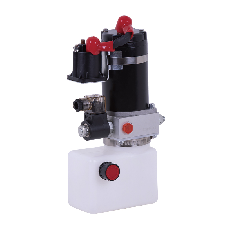
This hydraulic power unit is specially designed for all electric pallet truck.It consists of high voltage gear pump,permanent magnet DC motor and cent...
See Details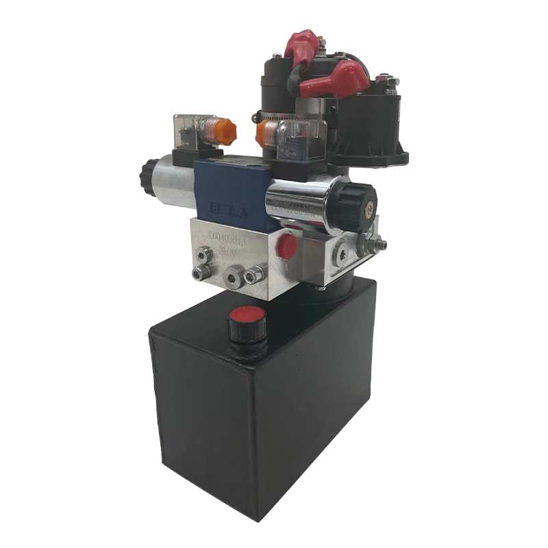
This portable stacker hydraulic power unit is designed for portable stackers and integrates a high-pressure gear pump, a permanent magnet DC motor, a ...
See Details
This hydraulic power unit of full electric stacker is specially designed for full electric stacker. It is integrated by a high-pressure gear pump, a D...
See Details
This hydraulic power unit is specially designed for dump trailers. It is integrated by a high-pressure gear pump, DC carbon brush machine, central val...
See Details
This hydraulic pump station is composed of a series of side inlet and side outlet gear pumps and 4.5 or 5-inch DC motors. It is often used as a hydrau...
See Details
This boarding axle power unit is specially designed for fixed boarding ramps and integrates a high-pressure gear pump, an AC motor center valve block,...
See Details
The hydraulic power unit is specially designed for the integrated shallow buried hydraulic lifting column, It integrates a bidirectional gear pump, AC...
See Details
This hydraulic power unit is specially designed for the three-dimensional parking garage and is integrated by a high-pressure vanepump, an AC oil imme...
See Details
The V3068 hydraulic valve group is an electric check valve group designed for hydraulic systems. It is mainly used to prevent the backflow of media, e...
See Details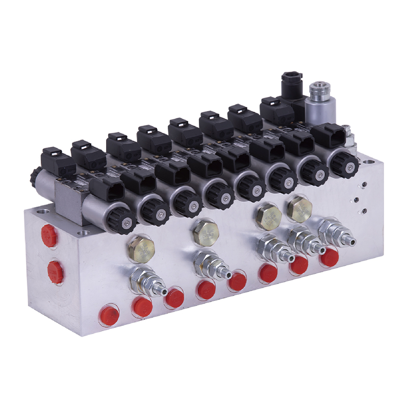
The modular hydraulic valve block uses modular integrated design to accurately combine multiple hydraulic valves, greatly simplifying the system pipel...
See Details
No. 12 Tongji Road, Simen Town, Yuyao City

+86-0574-62130352
+86-18905846028

+86-0574-62130353

Copyright© Ningbo Panic Hydraulic Technology Co., Ltd. All Rights Reserved. China Hydraulic Power Units Manufacturers

