


 English
 中文简体
中文简体 русский
DC micro power unit
Cat:DC series hydraulic power unit
This DC micro power unit combines high-pressure gear pumps, DC motors, center valve blocks, cartridge valves and oil tanks. It is compact and powerful...
See DetailsContent
A directional control valve is the steering wheel of any hydraulic circuit. It decides where the pressurized oil goes, which cylinder extends, which motor rotates, and how fast it happens. If your hydraulic power unit supplies flow but the valve is undersized, misapplied, or contaminated, the entire machine loses precision and uptime. This guide explains how to choose the right directional control valve for your equipment, what specifications actually matter, and how to avoid the most common mistakes.
If you are researching this topic as part of a broader hydraulic power unit project, you can explore your options on our main site for context on complete hydraulic power units and valve accessories.
A directional control valve is a mechanical or electro-mechanical device that changes the path of hydraulic fluid by shifting an internal element called a spool or poppet. In a hydraulic system, the pump generates flow, but it cannot decide which actuator should move. The directional control valve takes over that role by connecting selected ports in a specific configuration.
Most standard valves offer between two and four ports, and their spool can move to two or three positions. A two-position valve might be used for a simple cylinder that extends and retracts. A three-position valve typically has a center position where all ports are blocked, or where the pump is unloaded back to the tank. The neutral or middle condition is often designated as the center function, and it directly affects how the system behaves when the valve is not actuated.
Directional control valves fall into two broad families: spool valves and poppet valves. Spool valves handle higher flow rates and are easier to shift under pressure. Poppet valves provide extremely low leakage and clean sealing. For mobile equipment and static power units alike, the spool design is the industry default.
If you are still confused about how the oil path is actually reversed, our article on how the oil circuit direction is determined during hydraulic power unit operation explains the full logic in plain terms.
Directional control valves are classified by their number of positions, number of ports, the method of actuation, and the internal design. The most common configuration in industrial and mobile hydraulics is the four-way, three-position valve, often written as 4/3. The first number stands for the number of service ports, the second for the number of switching positions.
A 4/3 valve controls a double-acting cylinder, and it can also drive a bidirectional motor. A 3/2 valve is more common for single-acting cylinders or pilot control. A 2/2 valve is essentially a shut-off or on/off element.
| Type | Ports | Positions | Typical Application |
|---|---|---|---|
| 2/2 | 2 | 2 | Simple on/off flow control |
| 3/2 | 3 | 2 | Single-acting cylinder |
| 4/2 | 4 | 2 | Double-acting cylinder with fixed path |
| 4/3 | 4 | 3 | Double-acting cylinder with variable neutral |
Actuation methods are equally important. Manual valves use levers, handles, or pedals, and are common in mobile machine cabs. Solenoid valves use an electric coil to shift the spool, and are the standard choice in automated systems. Pilot-operated valves use a small pilot pressure to move a larger spool, which allows compact solenoids to control high-flow circuits.
Proportional valves represent a separate category. Instead of only switching paths, they modulate the spool position continuously. This allows pressure and flow to be regulated gradually. In many modern hydraulic power units, a proportional directional valve replaces both a directional control valve and a flow control valve.
For buyers, the choice between manual, solenoid, and proportional actuation determines whether the machine can be automated, how much electrical power is needed, and what control system can be connected.
The working principle is based on shifting a spool inside a precision-ground bore. The spool lands are machined so that, at certain spool positions, specific port connections are opened or blocked. When the spool moves to the left, pump flow is directed to the cylinder's cap end, and the rod end connects to the tank. When the spool shifts to the right, the connections swap. When the spool is centered, the center function determines the outcome.
The response time of a standard solenoid valve is in the range of 30 to 80 milliseconds, depending on the coil voltage. For safety-critical circuits, faster response means lower risk of pressure spikes. In high-flow circuits above 60 L/min, the spool diameter and the spring rate increase, so response time can exceed 100 ms.
The center function is a crucial selection factor. A closed center valve blocks all ports and delivers full pressure to the actuator with zero leakage. An open center valve connects pump to tank directly, providing the easiest turnkey operation. A tandem center valve unloads the pump at low pressure, which reduces heat generation in standby conditions.
Your hydraulic power unit creates pressurized flow, but without a directional control valve it cannot perform any useful work. In compact power units, the directional control valve is often assembled into a manifold block or a valve group, so that the complete pump, tank, and control stack forms one functional package.
Ningbo Panic Hydraulic Technology Co., Ltd. designs power units around directional control valves from the very beginning. The valve group is not an afterthought. For example, in the ET series hydraulic lifting platform valve group, the directional control function is integrated with overload protection and pressure compensation, giving the platform a stable speed under varying loads.
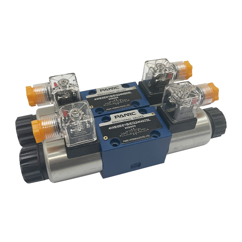 Hydraulic Solenoid Valve for Directional Control in Power UnitsThis solenoid valve switches hydraulic oil passages rapidly, making it a key component for precise actuator control in systems built around directional valve configuration.View Product →
When you order a standard power unit, the directional valve configuration determines the wiring, the tank size, and the manifold layout. The movement of a DC motor pump station is reversed either by changing the electrical polarity of a reversible motor or by using a directional valve that changes the flow while the motor runs in one direction. The second approach is more common in our DC series because it simplifies wiring and control.
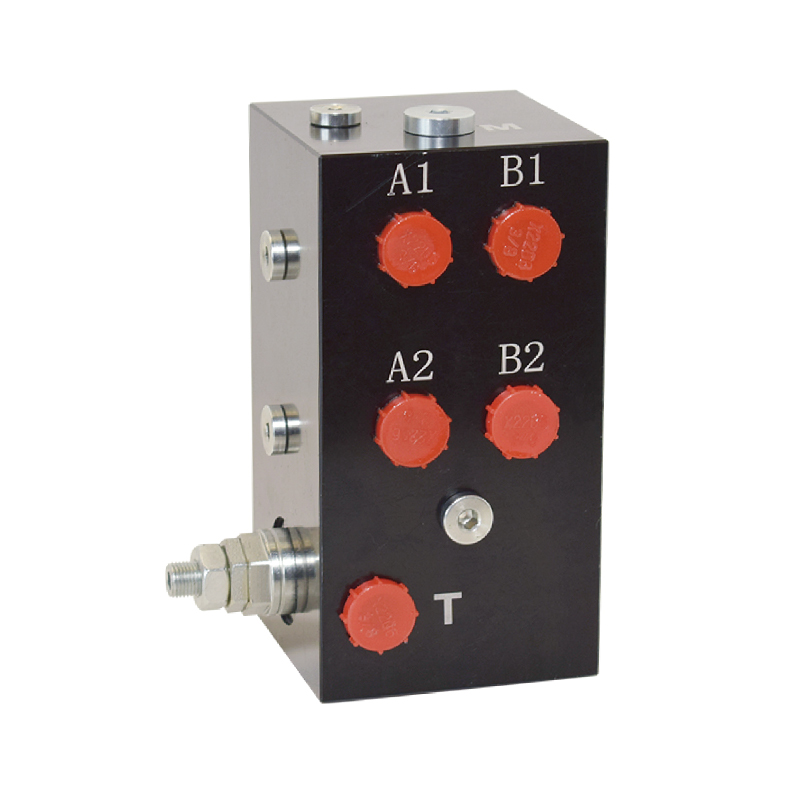 Integrated Hydraulic Valve Block for Compact Manifold AssemblyThis valve block mounts multiple valves with precision-machined flow channels, reducing hoses and leaks while supporting modular control stacks for various power units.View Product →
Hydraulic valve blocks and integrated manifold valve groups are available in several configurations, from a two-unit block to a four-unit block. When a directional control valve is inserted into such a block, the result is a highly modular control stack that supports a wide range of actuators without requiring a large number of separate hoses and fittings.
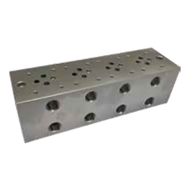 Multi-connection Integrated Valve Block with Two to Four UnitsAvailable in two-, three-, or four-unit versions, this block integrates several functions to optimize oil paths, simplify installation, and improve system stability for industrial machinery.View Product →
The key advantage of this modular approach is serviceability. If one valve section fails, the technician can remove that component and replace it without draining the entire system, which cuts downtime in busy production environments.
The correct valve specification is decided by four factors: flow rate, pressure rating, valve function, and control type. Getting any one of them wrong leads to either sluggish machine movement, premature failure, or energy waste.
Select the valve with a nominal flow rating equal to or slightly above the maximum system flow. A valve rated for 40 L/min operating at its limit produces high pressure drop, which converts into heat. Standard industry practice recommends operating at 70 to 80 percent of the rated flow for continuous duty. For example, if your pump delivers 25 L/min, choose a valve with a 30 to 35 L/min rating.
The valve's maximum working pressure must exceed the system's relief valve setting. If the relief is set at 25 MPa, the valve should be rated for at least 31.5 MPa. Most manufacturers publish pressure ratings that follow ISO 4413 standards, so a 31.5 MPa rating is common in mobile equipment.
Choose the neutral condition based on your load type. If you need the cylinder to hold its position when the valve is centered, use a closed center valve. If your power unit runs continuously with a large reservoir, an open center can shorten the warm-up time. For most battery-powered mobile applications, a tandem center is ideal because it unloads the pump during idle intervals.
Solenoid controls allow connection to PLC and remote systems. Manual controls give the operator direct tactile feedback. Proportional controls deliver smooth acceleration and deceleration, which is critical for heavy loads that could swing violently on a simple directional valve.
Additionally, the valve should be selected in relation to the system's filtration level. Typical mobile hydraulic circuits require ISO 4406 cleanliness of 19/17/14 or better. Using a valve beyond its recommended contamination tolerance leads to spool stiction, internal leakage, and shortened service life.
| Center Function | Pump Connection | Actuator Hold | Best Use |
|---|---|---|---|
| Closed Center | All ports blocked | Excellent | Load-holding circuits, clamping |
| Open Center | Pump to tank | Not available | Open-loop systems, low-cost circuits |
| Tandem Center | Pump to tank | Not available | Mobile systems, battery power |
Directional control valves appear wherever hydraulic movements must be precise and repeatable. In the material handling industry, the steering of a pallet truck or the tilting of a dump trailer is handled by the valve's shifting action combined with the power unit.
In machine tool systems, the control valve routes coolant and cutting oil to the right cylinder at the right moment. For a clamping circuit, the valve must shift quickly to lock the workpiece, and the center position must hold the clamping force so the part does not move during machining.
In lifting equipment such as dock levelers and scissor lifts, the valve's neutral position is often a load holding position. A pilot-operated check valve is used together with the directional valve to prevent the platform from creeping downward.
Fast-moving logistics operations rely on directional control valves more than people think. Every electrohydraulic stacker, every truck tail lift, and every mobile lifting platform depends on the same basic valve, whether it is manually shifted or operated by a pushbutton.
For a mini pallet truck, the directional valve is often a compact 3/2 solenoid valve mounted directly on the pump. When the operator presses the button, the solenoid shifts and directs flow to the lifting cylinder. When the button is released, the spring returns the spool and the cylinder holds the load. This simple cycle repeats thousands of times per day.
In automotive tail lifts, the valve needs to handle both lifting and tilting functions, often with a single directional valve combined with a flow divider. The valve group must work reliably outdoor in rain, dust, and temperature extremes, which is why the sealing specification matters as much as the flow rating.
Three issues account for most valve failures: spool stiction, internal leakage, and solenoid burnout.
Spool stiction usually results from contaminated oil. Particles and fine debris wedge into the clearance between the spool and sleeve. The remedy is replacing the oil filter and flushing the circuit. If the spool still sticks, disassemble the valve and inspect the bore for scratches.
Internal leakage occurs when the spool lands are worn or when the sealing edges are damaged. The leakage path allows pressure to bypass the actuator, and the machine loses speed. A quick check is to measure the pressure drop across the valve while the actuator is held against a stop. An increase in bypass flow indicates worn spool edges.
Solenoid burnout is often a sign of low voltage. The coil draws higher current when the system voltage is below the rated value, which raises the temperature and ultimately burns the insulation. Another common cause is switching frequency. Rough sequence control that shifts the valve more than ten times per minute creates thermal stress. In that case, a higher duty rated coil is needed.
Preventive maintenance includes checking the coil resistance against the manufacturer's specification, verifying the electrical connector is clean and tight, and confirming that the oil temperature does not exceed 60 degrees Celsius for standard seals. At 60 degrees, the service life of a typical O-ring is roughly half of what it would be at 40 degrees.
A directional control valve only changes the path of the fluid. It does not restrict flow. A flow control valve adds an intentionally sized restriction that regulates the amount of fluid passing through it. In many systems, a proportional directional valve performs both functions.
Yes. A four-way valve controls a double-acting cylinder and also reverses the rotation of a hydraulic motor. The motor's speed depends on the flow, and its direction depends on which ports are pressurized.
For mobile hydraulics, most standard spool valves have a maximum pressure from 25 to 35 MPa, depending on the manufacturer and the port size. The valve should always be specified above the system setting of the relief valve.
Under normal industrial conditions, a monthly visual check and an annual functional test are common. In high duty cycles with 24-hour operation, the oil should be analyzed monthly and the valve should be checked for response time every six months.
Yes. The exterior can be wiped to prevent dust from entering the spool bore. The internal filtration should be maintained by replacing the filter cartridges at the intervals recommended by the system designer.
A hydraulic valve block is a machined manifold that houses multiple directional valves, relief valves, and check valves in one compact body. It reduces the number of hoses and fittings, making the system more reliable and easier to service.
Choosing the right directional control valve is not a technical luxury. It is a functional requirement. A correctly sized valve increases machine uptime, reduces energy consumption, and simplifies future maintenance. Whether you are building a hydraulic tailboard, a lifting platform, or a full hydraulic station, the valve that directs the oil determines whether the machine performs as intended.
Start with the flow and pressure numbers. Confirm the center condition that fits your circuit. Decide whether a manual, solenoid, or proportional valve suits the operator's environment. Then confirm the cleanliness level of your oil. These four parameters cover most of the critical difference between a reliable circuit and a chronic problem.
If you are specifying a hydraulic power unit, always review the valve group together with the pump and tank. The directional control valve interacts with both, and a mismatch at any point causes heat, noise, or loss of control.

This DC micro power unit combines high-pressure gear pumps, DC motors, center valve blocks, cartridge valves and oil tanks. It is compact and powerful...
See Details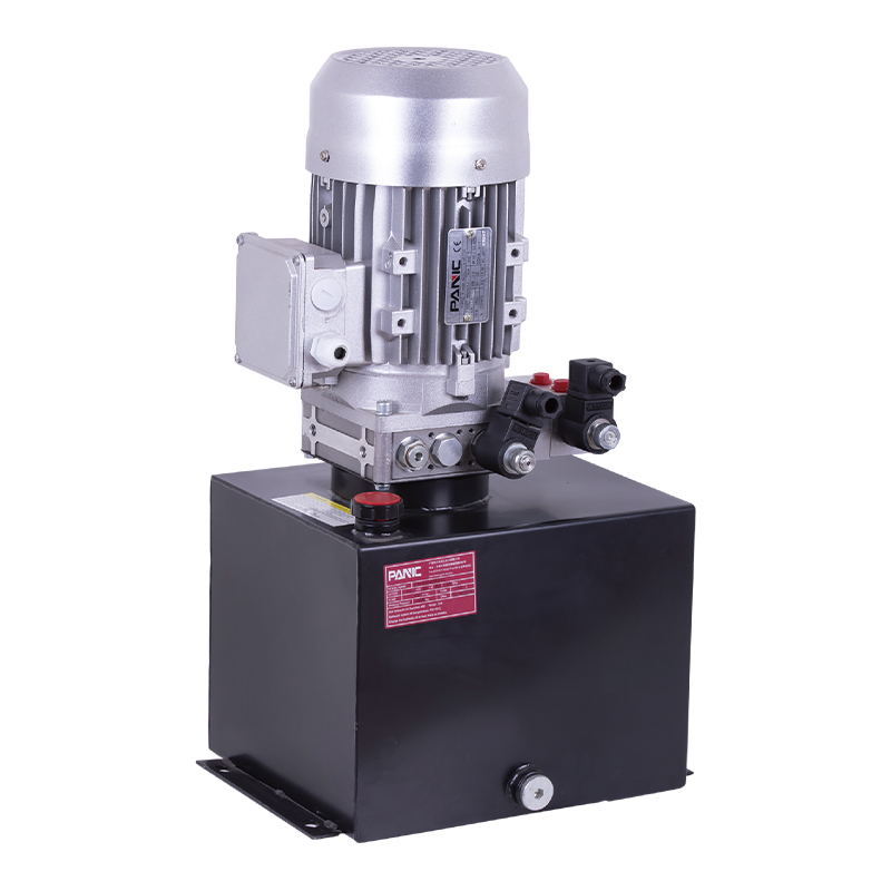
This hydraulic power unit is designed for scissor lifts and integrates a high-pressure gear pump, AC motor, center valve block, cartridge valve and oi...
See Details
This hydraulic power unit is designed for telescopic belt conveyors. It integrates a high-pressure gear pump, AC motor, center valve block, cartridge ...
See Details
The hydraulic power unit is specially designed for the integrated shallow buried hydraulic lifting column, It integrates a bidirectional gear pump, AC...
See Details
This hydraulic power unit is specially designed for a split hydraulic lifting column, It integrates a bidirectional gear pump, AC oil-immersed motor, ...
See Details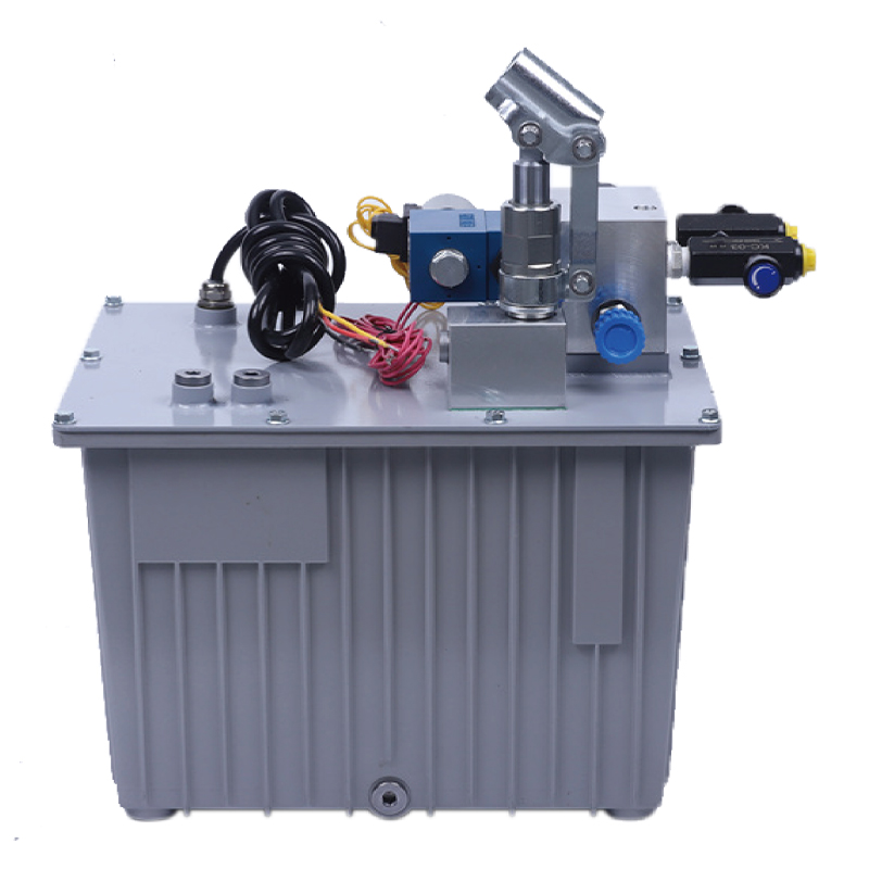
This hydraulic power unit is specially designed for an anti-terrorism hydraulic roadblock machine. It is integrated by a high-pressure gear pump, an A...
See Details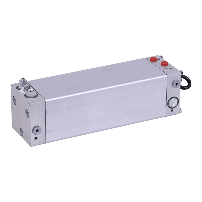
This oil immersed bidirectional pump power unit is designed for various types of mechanical equipment. It integrates a high-pressure bidirectional gea...
See Details
This oil immersed double actina power unit is designed for efficient, compact and low noise applications, integrating high pressure gear pump, AC oil ...
See Details
The V3068 hydraulic valve group is an electric check valve group designed for hydraulic systems. It is mainly used to prevent the backflow of media, e...
See Details
Proportional valve is a key component for realizing continuous and precise control of flow or pressure in hydraulic system. It can adjust output param...
See Details
No. 12 Tongji Road, Simen Town, Yuyao City

+86-0574-62130352
+86-18905846028

+86-0574-62130353

Copyright© Ningbo Panic Hydraulic Technology Co., Ltd. All Rights Reserved. China Hydraulic Power Units Manufacturers

