


 English
 中文简体
中文简体 русский
Hydraulic tailboard power unit
Cat:DC series hydraulic power unit
This hydraulic power unit is specially designed for the hydraulic tail plate. The vehicle tail plate hydraulic power unit is a power unit used for the...
See DetailsContent
Among the questions we hear most often from buyers of hydraulic power units, one stands out: "What size do I need?" It usually arrives with a list of cylinder dimensions, a target lifting speed, and a power source. The short answer: size the unit around the three numbers that govern everything else — flow, pressure, and duty cycle. Flow determines speed, pressure determines force, and duty cycle determines how much heat the unit must shed. Every other choice, from pump displacement to motor power and reservoir volume, is derived from these three.
This guide walks you through a practical sizing sequence with formulas, worked examples, and selection criteria that you can apply directly to lifting platforms, docking equipment, machine tools, tail lifts, and many other applications. The goal is straightforward: give you a correctly sized power unit — not one that is overbuilt, underpowered, or prone to overheating.
Every hydraulic power unit sizing exercise reduces to three governing numbers. Flow rate, expressed in litres per minute, controls how fast a cylinder extends or a hydraulic motor rotates. Pressure, expressed in bar, controls how much force the actuator can deliver. Duty cycle, expressed as a percentage, controls the thermal load that the reservoir, cooler, and components must absorb. Once these three are fixed, the pump displacement, motor power, valve size, and reservoir volume all become arithmetic.
Consider a lift table that requires a 500 mm stroke, a lift time of five seconds, and a fully loaded force of 20 kN. Typical instinct says “buy a bigger motor to be safe”. The calculations show a different story: the flow works out to about 18.7 L/min, the pressure to about 64 bar, and the correct motor power to roughly 2.2–3 kW. Choosing a 4 kW or 5.5 kW motor adds 30–50% to the cost, increases idle power consumption, and often produces more heat than the system actually generates under normal cycling. Starting with the three governing numbers eliminates this kind of waste before it happens.
The table below summarises the primary parameters used in sizing a hydraulic power unit. These values apply to typical industrial and mobile units in the 0.5–40 L/min range, which covers the majority of lifting platforms, cargo lifts, tailboards, dock levellers, machine tools, and roadblock systems.
| Parameter | Unit | Typical Range | Why It Matters |
|---|---|---|---|
| Flow rate | L/min | 0.5 – 40 | Determines actuator speed and cycle time |
| Operating pressure | bar | 50 – 250 | Determines force available at the actuator |
| Motor power | kW | 0.25 – 7.5 | Must match the product of flow and pressure |
| Reservoir capacity | L | 2 – 5 × pump flow | Affects heat rejection and oil turnover |
| Duty cycle | % | 5 – 100 | Governs thermal load and component grade |
| Oil viscosity | cSt | 32 – 68 | Influences leakage, noise, and cold-start performance |
In practice, you do not need to spec every parameter perfectly on the first pass. The sizing flow below moves from the cylinder to the pump to the motor so that each value supports the next one.
The correct sizing sequence always starts with the actuator and the motion profile. No reliable figure can be calculated for pump flow or motor power until the cylinder bore, stroke, cycle time, and load are known. The steps below follow that order.
Write down the following values for each actuator in the system:
For scissor lifts or tilting mechanisms, the required cylinder force is not simply the payload divided by the piston area. The mechanical linkage multiplies force according to the platform angle, so use the manufacturer's load chart or a free-body calculation to find the worst-case cylinder load near the bottom position.
Use the cylinder cross-section area and stroke to get the displaced oil volume, then divide by the required movement time:
A = π × D² / 4
V = A × stroke
Q = V × 60 / t
Where A is the piston area in cm², D is the cylinder bore in cm, stroke is in cm, V is the displaced volume in millilitres (cm³), t is the extend time in seconds, and Q is the flow rate in L/min.
Worked example: A 63 mm bore cylinder with a 500 mm stroke must extend in 5 seconds. A = π × 6.3² / 4 = 31.17 cm². V = 31.17 × 50 = 1558 mL. Q = 1558 × 60 / 5 = 18.7 L/min. Add a 10–15% margin for internal leakage and wear: design flow ≈ 21 L/min.
Pressure is force divided by area, expressed in bar. Include the pressure drop through the directional valve, check valves, and piping, which typically adds 5–10 bar in a compact power unit.
p (bar) = F (N) / A (cm²) / 10
Using the same cylinder: p = 20,000 N / 31.17 cm² / 10 = 64.2 bar. With valve losses, design pressure becomes about 70 bar. Set the relief valve at 80 bar, which is roughly 15–20% above the working pressure.
At a given motor speed, the gear pump displacement is calculated as:
Vg (cm³/rev) = Q (L/min) × 1000 / (n (rpm) × ηv)
Assuming a 1450 rpm AC motor and a volumetric efficiency of 0.92 for a typical gear pump: Vg = 21 × 1000 / (1450 × 0.92) = 15.7 cm³/rev. Choose the next standard size, 16 cm³/rev, which delivers approximately 21.3 L/min.
Motor power follows from flow and pressure:
P (kW) = p (bar) × Q (L/min) / (600 × ηt)
With a total efficiency (pump + motor) of roughly 0.85: P = 70 × 21.3 / (600 × 0.85) = 2.92 kW. Select a 3 kW AC motor, the next standard size above 2.2 kW.
The table below gives four worked examples using this exact method. All values assume a 1450 rpm AC motor and include a 12% flow margin.
| Cylinder bore (mm) | Stroke (mm) | Extend time (s) | Load (kN) | Flow (L/min) | Pressure (bar) | Motor power (kW) |
|---|---|---|---|---|---|---|
| 40 | 300 | 3 | 10 | 8.5 | 80 | 1.5 |
| 50 | 400 | 4 | 15 | 13.2 | 76 | 2.2 |
| 63 | 500 | 5 | 20 | 21.0 | 64 | 3.0 |
| 80 | 600 | 6 | 30 | 34.0 | 60 | 4.0 |
For a ready-made matched solution in this power range, many buyers turn directly to a dedicated lifting platform power unit. These units integrate pump, valve group, reservoir, and motor in one assembly, eliminating the risk of mismatched components.
 Integrated Lifting Platform Power Unit with Pressure CompensationThis unit combines pump, motor, valve block, and tank for lifting platforms. Its pressure compensation valve keeps descent speed steady under varying loads, and motor and tank options suit different duty cycles.View Product →
A general rule of thumb: for intermittent industrial duty, the reservoir should hold 2–3 times the pump flow per minute; for continuous duty, use 3–5 times. In the worked example, a 21 L/min pump needs a 40–60 L reservoir for continuous work, or a 20 L tank for short-cycle mobile applications. The reservoir serves as both an air separator and a heat sink, so undersizing it will cause foaming and rapid oil degradation.
If you are sizing a unit for a DC-powered or compact machine, the same formulas apply but the motor speed differs (typically 2800–4000 rpm for DC motors). The pump displacement gets smaller at higher speed, and the motor current must be checked against the battery or alternator capacity. The basic working principle of a hydraulic system remains the same regardless of the power source.
Duty cycle is the percentage of time the pump actually delivers oil under pressure during one working period. A machine that runs for 30 seconds and then idles for 30 seconds has a 50% duty cycle. A dock leveller that lifts three times per hour has a duty cycle close to 2%. The relationship is:
Duty cycle (%) = ton / (ton + toff) × 100
The efficiency of a gear-pump power unit is typically 80–90%. The remaining energy converts to heat. For a unit producing 2.68 kW of hydraulic power at 85% efficiency, about 0.4 kW must be rejected. In a 40 L reservoir with natural convection, this keeps oil temperature under roughly 70°C in ambient conditions up to 40°C. If the duty cycle exceeds 50%, add an oil cooler or increase the reservoir volume by another 20–30%.
Continuous-operation machines such as hydraulic cargo lifts, parking lifts, and long-stroke lifting columns often benefit from an oil-immersed power unit, where the motor and pump run submerged in the reservoir. This design runs quietly, dissipates heat directly into the oil, and occupies less space than a separate tank and frame.
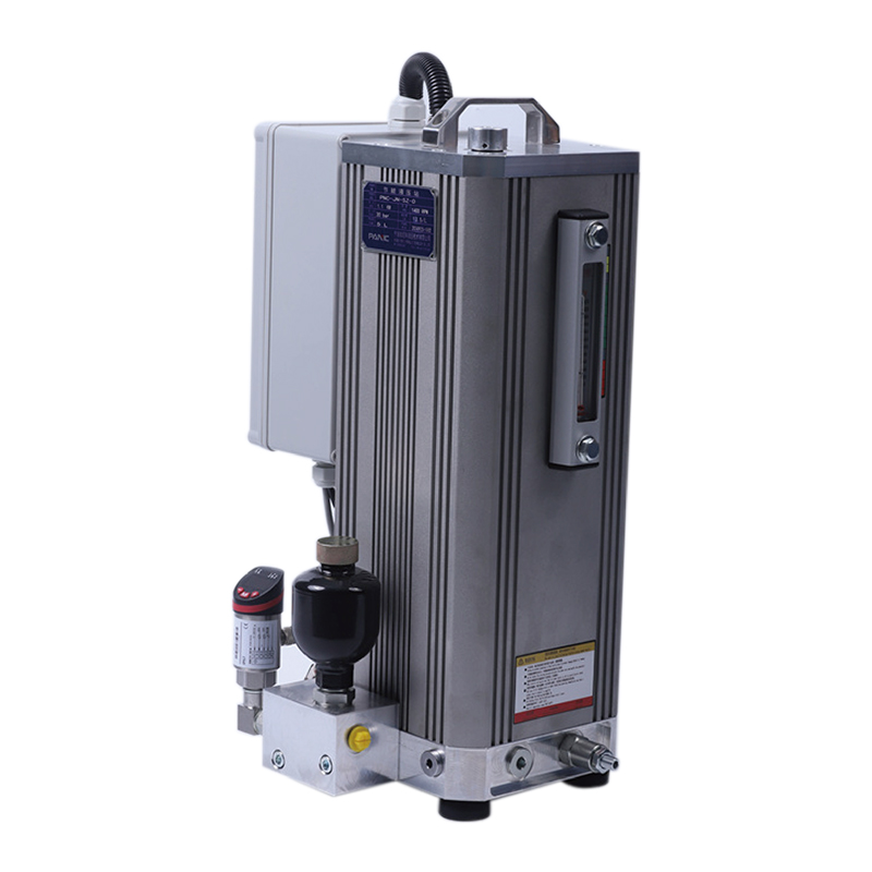 Accumulator-Based Energy-Saving Hydraulic Power StationDesigned for long-pressure-holding applications like machining centers, this station uses an accumulator to stop the motor during idle periods, cutting power use, noise, and heat while extending equipment life.View Product →
The core flow and pressure formulas are identical for all power unit types. The differences appear in motor speed, current draw, and heat management.
AC units run at 1450 rpm (4-pole, 50 Hz) or 1740 rpm (4-pole, 60 Hz). They are the default choice for industrial equipment that has a stable mains supply — lifting platforms, machine tools, conveyors, and dock equipment. The sizing table in the previous section applies directly to AC units.
DC units operate from 12 V, 24 V, or 48 V batteries, and are used in tail lifts, pallet trucks, mobile lifting platforms, and self-dumping trailers. DC motors spin at 2800–4000 rpm, so the pump displacement for a given flow is roughly half that of an AC gear pump. The motor current is a critical check:
I (A) = P (W) / (U (V) × ηmotor)
A 1.5 kW motor on a 24 V system draws roughly 74 A — the battery cable cross-section, fuse rating, and contactor size must all be matched to that current. If the application is highly intermittent and the space is tight, a compact DC motor pump station is often the cleanest packaging solution.
 Compact DC Micro Power Unit for Double-Acting CylindersBuilt for tight spaces, this DC unit powers double-acting hydraulic cylinders via a cartridge solenoid valve. With 12–48 V options and compact packaging, it suits intermittent tasks in marine, automotive, and logistics equipment.View Product →
Oil-immersed units place the pump, motor, and valves directly inside the reservoir. They are quieter and more compact than conventional units, making them an established choice for hydraulic lifting columns, anti-terrorism bollards, parking garage lifts, and hydraulic cargo elevators. Because the motor resides in oil, heat is transferred directly to the fluid, which improves cooling during continuous cycling. The reservoir size in these units can be smaller than the 3–5 rule would suggest, since the motor heat is put directly into the oil rather than radiating into the cabinet.
In our experience supporting hydraulics buyers, six mistakes appear more often than any others. Each one has a predictable symptom and a straightforward prevention.
| Mistake | Typical Consequence | Prevention |
|---|---|---|
| Oversizing the motor “to be safe” | 30–50% higher cost and higher idle power draw | Calculate power from measured flow and pressure |
| Ignoring pressure drop across the directional valve | Cylinder force falls short at the rated load | Add 5–10 bar for valve and piping losses |
| Sizing for extension only, ignoring retract flow | Slow return stroke; reduced cycle throughput | Check single-acting differential area or use regenerative circuits |
| Using a reservoir far smaller than recommended | Oil foaming and overheating after 30 minutes | Keep 2–5 times pump flow in the tank |
| Setting the relief valve too high | Pump overload and premature wear | Relief set at working pressure plus 15–20% |
| Neglecting cold-start viscosity in low ambient temperatures | Cavitation, noise, and long first-cycle delay | Use 32 cSt oil in cold climates or add a small oil heater |
The three most important parameters are flow, pressure, and duty cycle — but flow is usually the one that gets calculated first. If the flow is wrong, the actuator speed is wrong, and no amount of pressure setting can fix it. Get flow right first, then confirm pressure and duty cycle before moving to the motor and reservoir.
A margin of 10–15% is reasonable for a new gear pump system. Add more if the cylinder seals are old, the pipe runs are long, or the pump has over 10,000 hours of service. Do not exceed 20% unless you are planning future capacity, as the extra flow raises motor power and cost.
Only if both machines require the same flow, pressure, and duty cycle. A unit sized for a slow, high-force press is unlikely to satisfy a fast, low-force lift table. Using one unit for two tasks forces you to compromise on either speed or force, and usually results in one machine underperforming.
The motor will draw overcurrent, heat up, and trip its thermal overload protection. Under continuous operation, the motor winding temperature rises above the rated class, which shortens insulation life. In a severe case, the motor burns out completely, and the pump may also be damaged by the resulting vibration and cavitation.
Gear pumps are the standard choice for 50–200 bar applications and flow rates up to roughly 40 L/min. They are simple, cost-effective, and tolerant of moderate contamination. Piston pumps become worthwhile above 200 bar, or when proportional flow control and variable displacement are required. For most lifting and clamping applications, a gear pump is the correct balance of cost and reliability.
Cold oil has a much higher viscosity, sometimes above 400 cSt at −20°C. The pump struggles to draw oil from the reservoir, leading to cavitation and slow pressure build-up. Two fixes are common: switch to a 32 cSt viscosity grade for cold climates, or add an electric immersion heater in the reservoir that warms the oil before start-up.
Before you send a specification to a hydraulic power unit manufacturer, run through this checklist:
A correctly sized hydraulic power unit delivers the intended speed and force, runs at a stable oil temperature, and does not waste energy. The few minutes spent on these calculations typically save weeks of troubleshooting later. If you need assistance matching a power unit to your specific cylinder and cycle requirements, our engineering team can review your figures and recommend the appropriate unit from the AC, DC, or oil-immersed series.
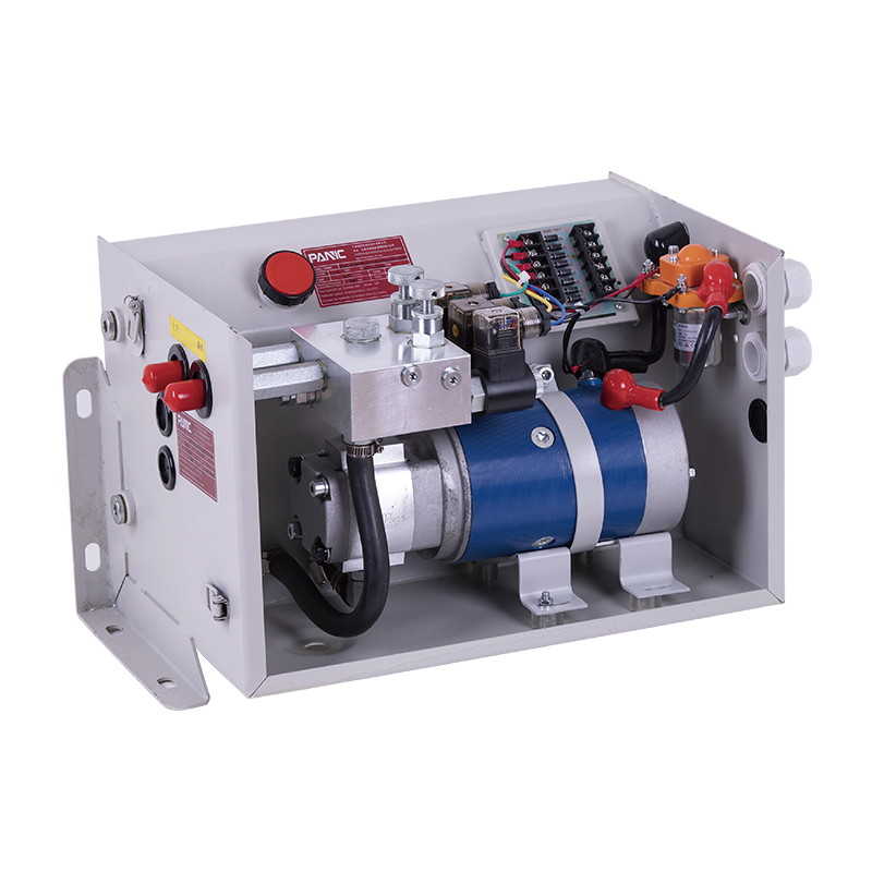
This hydraulic power unit is specially designed for the hydraulic tail plate. The vehicle tail plate hydraulic power unit is a power unit used for the...
See Details
This hydraulic power unit is specially designed for the clamping cylinder of the machine, too. It is integrated by a high-pressure gear pump.AC motor,...
See Details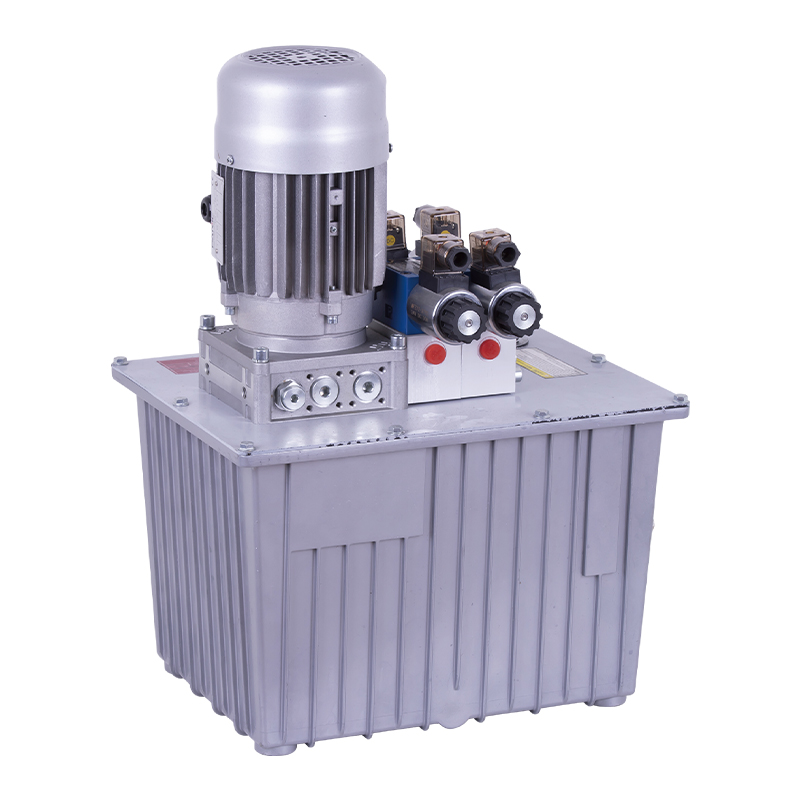
This hydraulic power unit is specially designed for a double-acting oil cylinder system, which is integrated by a high-pressure gear pump, an AC motor...
See Details
The hydraulic power unit is specially designed for the integrated shallow buried hydraulic lifting column, It integrates a bidirectional gear pump, AC...
See Details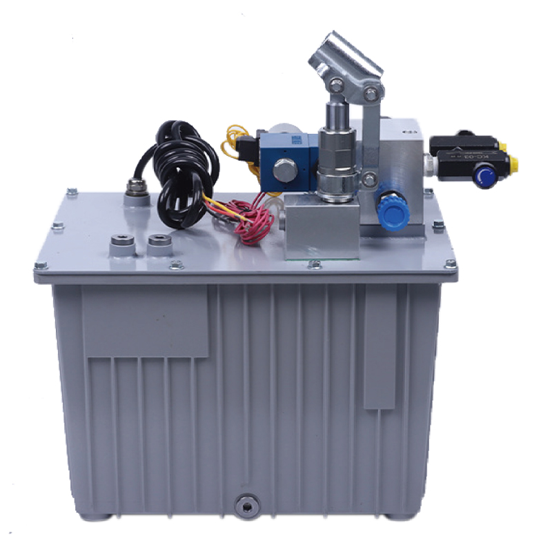
This hydraulic power unit is specially designed for an anti-terrorism hydraulic roadblock machine. It is integrated by a high-pressure gear pump, an A...
See Details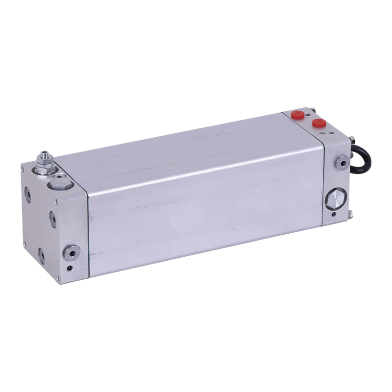
This oil immersed bidirectional pump power unit is designed for various types of mechanical equipment. It integrates a high-pressure bidirectional gea...
See Details
This hydraulic power unit is specially designed for hydraulic cargo elevators and is integrated with a high-pressure vane pump, AC Oil immersion motor...
See Details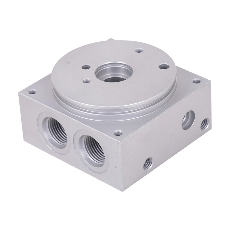
The power unit manifold block for lifting platform is the core integrated component of the hydraulic system, and plays a key role in coordinating vari...
See Details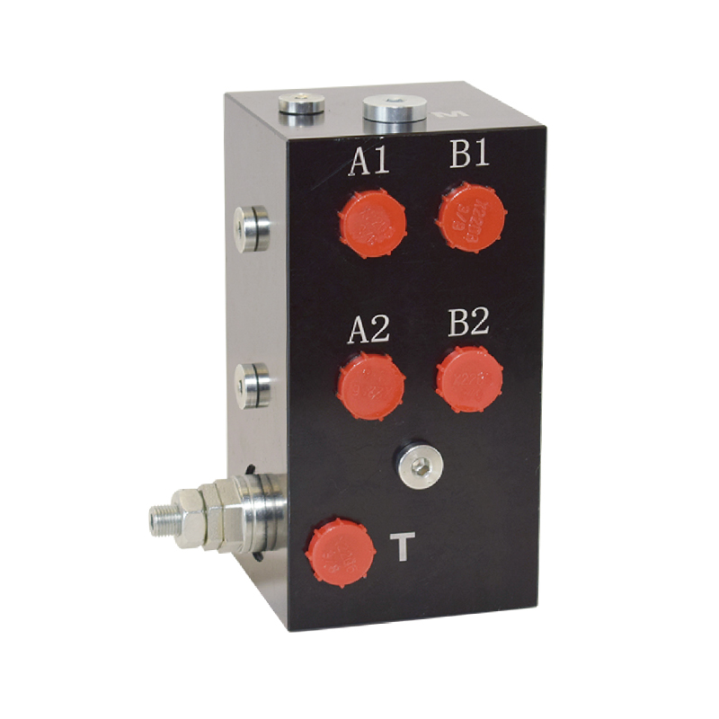
The hydraulic valve block centrally installs various hydraulic valves through the internal precision flow channel, solves the problems of bloated and ...
See Details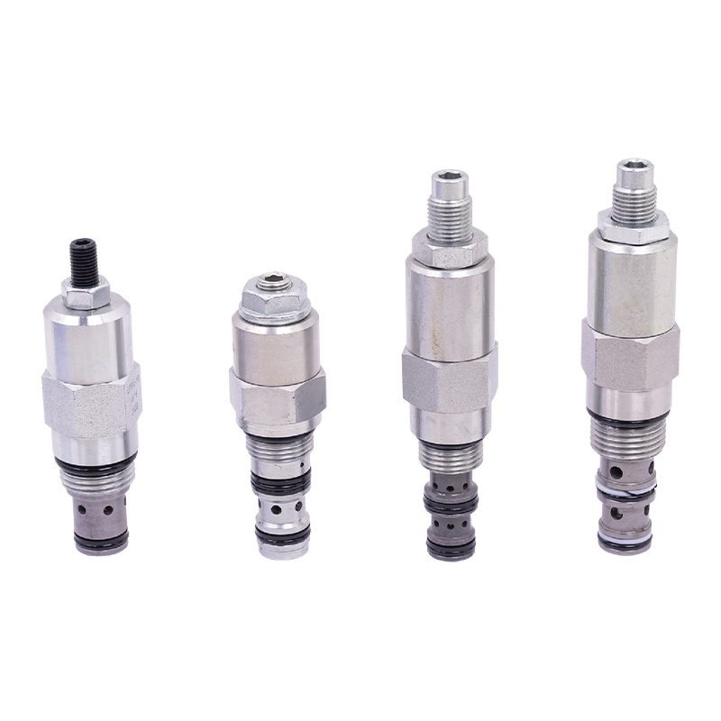
The regulating valve is a key device used in industrial control systems to adjust parameters such as fluid flow, pressure, and temperature. It can acc...
See Details
No. 12 Tongji Road, Simen Town, Yuyao City

+86-0574-62130352
+86-18905846028

+86-0574-62130353

Copyright© Ningbo Panic Hydraulic Technology Co., Ltd. All Rights Reserved. China Hydraulic Power Units Manufacturers

