


 English
 中文简体
中文简体 русский
Aerial vehicle electric pump
Cat:DC series hydraulic power unit
This hydraulic pump station is specially designed for a self-propelled aerial work vehicle. It is composed of 2 series side inlet and side outlet gear...
See DetailsContent
Your lift platform creeps upward roughly 30 mm after you release the handle. Your truck tailgate slams down the moment you crack a valve open. You adjust the same needle valve three times a day because cylinder speed keeps drifting as the oil warms up. These three failures look different, yet they all point to the same missing component: a hydraulic flow controller.
A hydraulic flow controller is a valve that sets the flow rate in a circuit and holds it close to that setting even when pressure or temperature changes. Because flow decides speed, the controller is the speed controller of the machine: it determines how fast a cylinder extends, how quickly a hydraulic motor spins, and how gently a suspended load lands. This guide covers what the hydraulic flow controller does, how it works, which type fits which circuit, how to size and install it, and what to do when it misbehaves.
A hydraulic flow controller regulates the volume of fluid passing through a line per unit of time, normally expressed in liters per minute (L/min) or gallons per minute (gpm). In a fixed-displacement pump circuit, the pump delivers a constant flow, and the controller bypasses or restricts part of that flow so only the intended amount reaches the actuator. In a proportional circuit, the controller meters flow continuously according to an electric input signal.
Put simply: flow controller equals speed controller. A cylinder takes its speed from flow, not from pressure. Double the flow and the same cylinder moves twice as fast; cut the flow in half and the motion time doubles. This is why speed complaints on a machine are almost always solved on the flow side of the circuit.
Flow control also matters for safety and energy. A hydraulic flow controller prevents a vertical load from running away, keeps two cylinders from racing each other, and trims pump demand during idle parts of a cycle. In practice, a correctly sized controller reduces pressure spikes, lowers cylinder and seal wear, and makes diagnostics easier because each actuator leg has a repeatable flow setting.
If the circuit layout is still unclear, read the working principle of a hydraulic system before touching the controller; once you see where the pump, tank, and actuator sit in the loop, the function of the controller becomes obvious.
A flow controller can be placed in three positions in a circuit, and each position changes the motion characteristics:
Every hydraulic flow controller builds on a simple physical rule: the flow through an orifice rises with the opening area and with the square root of the pressure difference across it. In a plain needle valve, this means flow changes whenever the load changes. At higher load pressure, the differential pressure falls and less oil passes; at lower load pressure, more oil passes and the actuator moves faster.
A pressure-compensated hydraulic flow controller solves this by adding a compensator spool that holds the pressure drop across the metering orifice nearly constant. The compensator senses the pressure on the inlet side and on the outlet side of the orifice. If the outlet pressure rises, the compensator shifts to open a bypass path or to close slightly, keeping the differential pressure at the value set by the spring. The flow therefore stays close to the selected value while the load pressure changes.
Typical catalog data for this class of components indicates that a good pressure-compensated controller holds flow within ±5 percent when the load pressure swings between 70 and 250 bar. A temperature-compensated version uses a thermal element to shift the metering edge as oil warms up, holding flow within roughly ±3 percent over a 20 °C to 60 °C oil-temperature band. Verify the figure against the data sheet of the exact valve you order, because tolerances differ between miniature and industrial sizes.
The same principle applies whether the controller is a small cartridge in a power unit manifold or a large inline valve on a press. The physical job is identical: convert a pressure-sensitive orifice into a pressure-stable metering edge.
You do not need every design in your plant. You need the one that matches your load pattern and your speed-stability target. The table at the end of this section compares them at a glance.
Needle valves and fixed orifices are the simplest devices. They are accurate only when the load pressure is stable. Use them for manual speed trimming on a machine whose load is nearly constant, such as a test bench or a small conveyor. They are the least expensive option and the easiest to maintain, but they cannot hold speed when the load changes.
The workhorse of industrial circuits. It keeps the flow setting across a wide pressure range, so cylinder speed stays stable while the machine is cutting, clamping, or lifting. This is the type commonly integrated into the port blocks and manifolds of hydraulic power units.
A temperature-compensated hydraulic flow controller adds a thermal element to the compensated design for long cycles and precision feeds where oil temperature climbs during the shift. The compensation element adjusts the effective opening as viscosity falls, which keeps cycle time repeatable from a cold start to a fully warm machine.
An electronically controlled proportional flow controller modulates flow in proportion to the input current or voltage it receives. It is effectively a variable orifice with a programmable opening, which means speed changes can be commanded mid-cycle by a PLC: slow approach, fast feed, slow retract, all in one valve. Proportional controllers are used on machine tool clamps and cutter feeds, tailboards with soft-stop motion, and mobile lifting platforms that need acceleration management. They cost more and need a tuning phase, but they remove the need for multiple fixed valves.
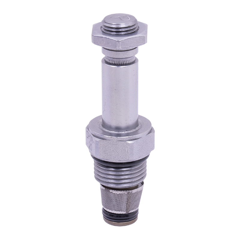 Electro-Hydraulic Proportional Flow Control Valve for Power UnitsThis proportional valve adjusts flow or pressure linearly with an electrical input, enabling smooth mid-cycle speed changes such as slow approach and fast feed. It suits machine tools and lifting platforms needing precise, programmable control.View Product →
A priority valve keeps a set flow to the priority port (for example, a steering circuit) and sends the remainder to a secondary circuit. A flow divider splits a single input into two proportional flows, which keeps two cylinders advancing in step even under an eccentric load. Both are special-purpose flow controllers that solve synchronization and control-routing problems.
A deceleration valve is a cam-operated or mechanically operated flow controller that gradually closes as the machine part approaches the end of stroke. It trims overshoot at the ends and prevents the hammer effect in fast machines.
| Type | Speed stability vs load | Speed stability vs temperature | Best use | Relative cost |
|---|---|---|---|---|
| Fixed orifice | Poor | Poor | Fixed-speed, steady-load circuits | Lowest |
| Needle / globe valve | Poor | Poor | Manual speed trimming, constant load | Low |
| Pressure-compensated | Good (±5%) | Moderate | Lifting platforms, machine feed, tailboards | Medium |
| Temperature-compensated | Good | Good (±3%) | Precision feed, long running cycles | High |
| Proportional | Good | Depends on electronics | Programmable, variable-speed cycles | Highest |
| Priority valve | Good for priority port | Moderate | Steering circuits, safety-critical priorities | Medium |
The first question on a sizing query is rarely the brand; it is the size. Five numbers matter when you compare hydraulic flow controllers for a power unit: rated flow range, maximum pressure, viscosity range, compensation accuracy, and port size or mounting pattern.
| Parameter | Typical range | Selection note |
|---|---|---|
| Rated flow | 0.5–80 L/min | Size 20–30% above actuator flow |
| Max pressure | 210–250 bar | Check dynamic peaks, not only nominal |
| Oil viscosity | 15–68 cSt | ISO VG 32 / VG 46 usually |
| Compensation | ±5% pressure; ±3% temperature | Tighter tolerance for precision feeds |
| Port size | G1/4–G1 | Match line size, avoid restrictors |
| Mounting | Inline, manifold, cartridge | Cartridge saves space in valve blocks |
A practical rule of thumb: choose a hydraulic flow controller whose rated flow is 20 to 30 percent above the maximum flow demanded by the actuator, then verify at the lowest supply pressure the pump delivers. Do not size a flow controller from the pump flow alone. The controller feeds one branch, not the whole pump, and an oversized valve is harder to adjust precisely at low flow settings.
Worked example: a lifting platform must raise in 8 seconds and needs 1.6 L of oil for the stroke. The actuator flow is 1.6 / 8 × 60 = 12 L/min, so a 15 L/min rated controller is the practical starting point.
Selection comes down to seven decisions. Walk through them in order, and you will end with a model that fits the machine instead of a part that merely fits the price.
The most frequent purchasing mistake is oversizing a flow controller from pump flow instead of actuator flow. A hydraulic flow controller can be too big: at small openings the metering edge becomes hypersensitive, and the speed is nearly impossible to set repeatably.
A new hydraulic flow controller usually works on the first test if the circuit is clean and the setting is made in the correct direction. These commissioning steps avoid the common failures.
Most hydraulic flow controller faults are contamination, misapplication, or wrong adjustment rather than a broken valve. This table lists the symptoms and the fastest route to a fix.
| Symptom | Likely cause | Action |
|---|---|---|
| Speed drops when load rises | Non-compensated design or worn compensator spool | Switch to compensated type; inspect and replace the spool |
| Speed climbs after warm-up | Oil viscosity drop with temperature | Use a temperature-compensated type |
| Flow stops completely | Stuck spool or blocked orifice | Disassemble, clean, check contamination level |
| Erratic speed or hunting | Compensator oscillation, weak spring, air in oil | Bleed air, check spring, increase load damping |
| Whistling or squealing | Cavitation or undersized ports | Increase line size, check suction filter |
In packaged power units, the hydraulic flow controller is rarely a separate inline component hanging in the hose. It is usually a cartridge or manifold-mounted regulator that sits in the same aluminum block as the relief valve, the check valve, and the directional valve. This configuration keeps the unit compact and the internal drillings short, which reduces leakage paths and pressure loss.
Three typical examples illustrate the combination. A lifting platform unit uses pressure-compensated flow control on the lowering leg so the platform does not accelerate while descending. A hydraulic tailboard unit uses meter-out control between the cylinder and the tank so a loaded tailgate cannot drop. A machine tool clamping unit uses proportional flow control to switch between fast approach and firm clamping of the same cylinder.
When you order a power unit, the flow control function should be decided at the same time as the pump and motor, because the valve group, tank return line, and the hydraulic flow controller must be matched as one package. For constant-speed motion with varying load, a compact regulating valve is the economic choice.
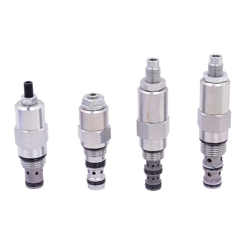 Power Unit Regulating Valve for Constant-Speed ApplicationsA compact regulating valve adjusts flow, pressure, or temperature with accurate response, making it an economical choice for constant-speed motion under varying loads. Available in pneumatic and electric versions for industrial systems.View Product →
For variable speed during the cycle, the proportional route gives the most flexibility. The capacity of the unit also matters: DC power units, for example, usually integrate flow controls in the 5 to 25 L/min range, while AC units extend to 80 L/min and higher. The lifting platform power unit is a good illustration of how the complete package, including pump, motor, tank, and flow control manifold, is designed around one transparent speed requirement. If you are in the middle of a replacement project, the manufacturer can also rebuild the manifold to fit existing ports.
 Hydraulic Lifting Platform Power Unit with Pressure CompensationThis integrated power unit includes gear pump, AC motor, center valve block, cartridge valve, and tank, with a pressure compensation valve for uniform descent under load. Motor power, voltage, and tank material are customizable.View Product →
Ningbo Panic Hydraulic Technology Co., Ltd. designs these valve groups in-house for its AC, DC, and oil-immersed series power units. Because the controller selection and the manifold drilling are handled together rather than piecemeal, the customer receives a matched assembly: flow controller, relief valve, tank, pump, and motor sized for the same duty cycle.
A hydraulic flow controller regulates flow, which sets actuator speed. A relief valve limits maximum pressure to protect the pump and components. They are complementary: the relief valve protects the circuit while the flow controller defines how fast the work moves. Many power unit manifolds contain both on the same block.
Only on a machine whose load is constant. A needle valve is an adjustable orifice with no compensation: when the load pressure changes, the flow through it changes and actuator speed drifts. If the load stays flat, a needle valve is an inexpensive speed trimmer; if it does not, choose a compensated type.
Use meter-out for a vertical cylinder that supports a load. The controller on the return line creates a back-pressure that supports the load and prevents free fall. Meter-in on a vertical cylinder risks the load overrunning the pump flow, which leads to cavitation and uncontrolled speed.
Viscosity falls as oil temperature rises, and a fixed orifice lets more oil pass at lower viscosity. The speed therefore climbs through the morning until the machine reaches thermal equilibrium. A temperature-compensated hydraulic flow controller removes most of that drift by moving a thermal element to close the metering edge as temperature rises.
Calculate the actuator flow: cylinder volume in liters divided by the required stroke time in seconds, multiplied by 60, gives L/min. Add a 20 to 30 percent margin, then choose a pressure-compensated type. For a platform that needs 12 L/min, a 15 L/min rated controller is the practical starting point.
Every metering step creates a pressure loss, so flow controllers are less efficient than a variable-displacement pump on continuous high-flow duty. For intermittent cycles, which is most power unit work, the flow controller is simpler, more compact, and easier to service. In a bypass regulator, the unused flow returns to the tank at low pressure, which keeps the energy loss modest.
Yes, if the pump has available flow and pressure and the manifold has a port for a proportional element. You also need a suitable amplifier driver and a control signal from the PLC or potentiometer. The hydraulic engineer should check the frequency response against the cycle time, because a proportional valve must be tuned, not just bolted on.
DC power units for tailboards, pallet trucks, and mobile lifting platforms commonly integrate hydraulic flow controllers in the 5 to 25 L/min range. The valve group is compact enough to mount directly on the motor-pump assembly while still leaving room for a relief valve and check valve.
A hydraulic flow controller does not need to be the most expensive component on a power unit to protect the most important property of the machine: predictable motion. The selection route is the same every time — actuator speed first, load type second, compensation level third, catalog last.
When you specify a new unit or replace a worn controller, start with those three decisions and the data tables in this guide. If you still need a hand with the sizing, Ningbo Panic Hydraulic Technology Co., Ltd. engineers its AC, DC, and oil-immersed series power units with in-house valve groups, so the flow controller, relief valve, tank, and pump are designed as one matched assembly.

This hydraulic pump station is specially designed for a self-propelled aerial work vehicle. It is composed of 2 series side inlet and side outlet gear...
See Details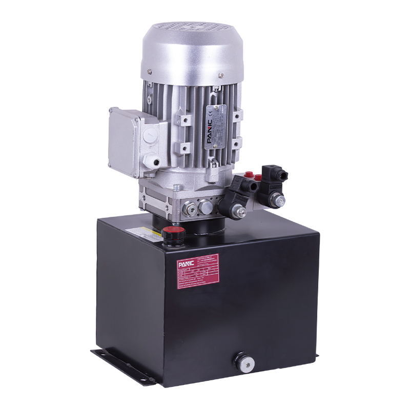
This hydraulic power unit is designed for scissor lifts and integrates a high-pressure gear pump, AC motor, center valve block, cartridge valve and oi...
See Details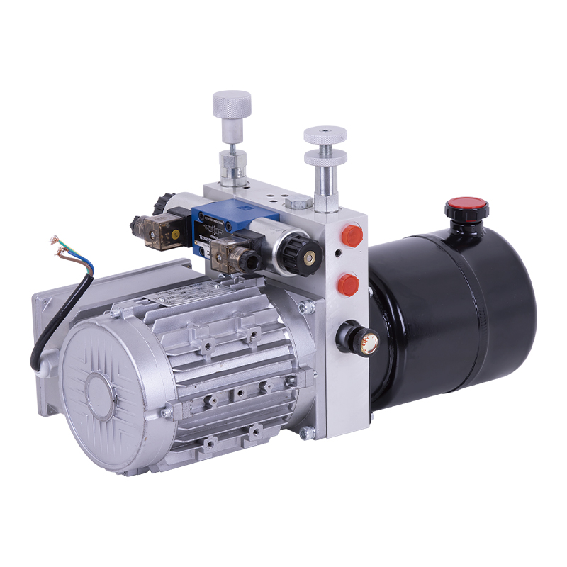
This hydraulic power unit is specially designed for hot-melt butt welding machine and is integrated by high-pressure gear pump, AC motor central valve...
See Details
This hydraulic power unit is specially designed for the storage flushing door and is integrated with a high-pressure gear pump, AC motor, central valv...
See Details
The hydraulic power unit is specially designed for the integrated hydraulic lifting column, which is integrated by a two-way gear pump, an AC oil imme...
See Details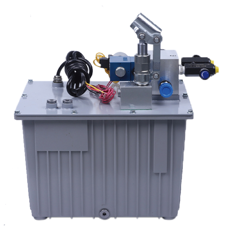
This hydraulic power unit is specially designed for an anti-terrorism hydraulic roadblock machine. It is integrated by a high-pressure gear pump, an A...
See Details
The V3068 hydraulic valve group is an electric check valve group designed for hydraulic systems. It is mainly used to prevent the backflow of media, e...
See Details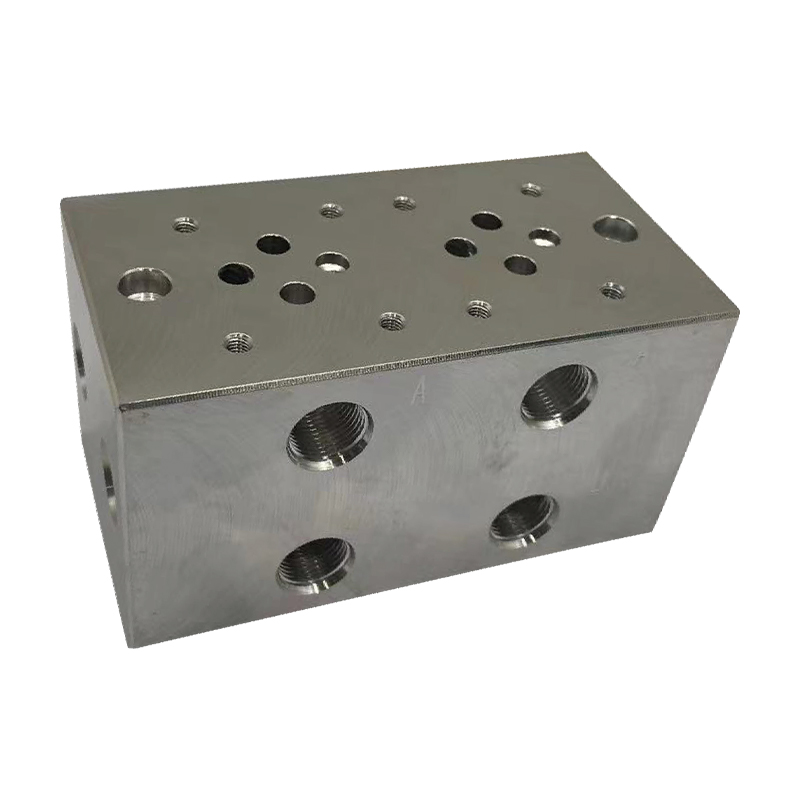
The multi-connection hydraulic integrated valve block is an efficient integrated component of the hydraulic system, including two-connection, three-co...
See Details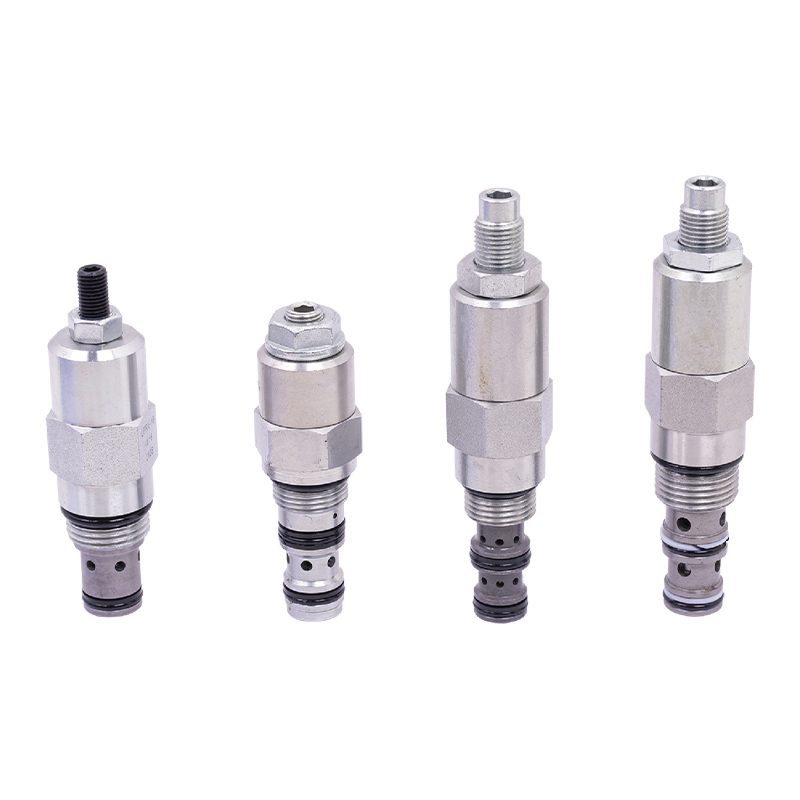
The regulating valve is a key device used in industrial control systems to adjust parameters such as fluid flow, pressure, and temperature. It can acc...
See Details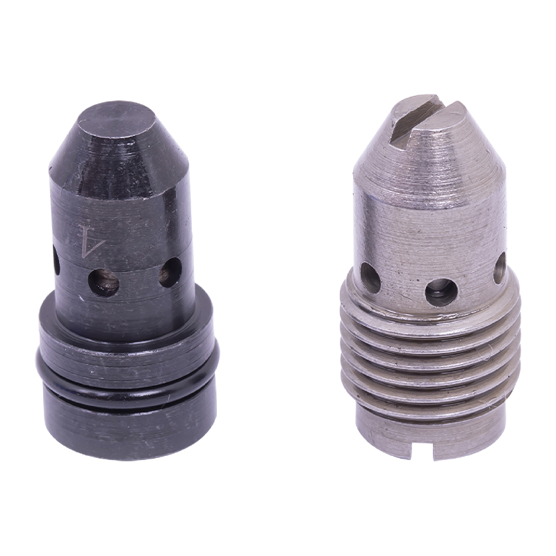
The pressure compensation valve is a key component in the hydraulic system to maintain flow stability. It can automatically adjust the valve opening w...
See Details
No. 12 Tongji Road, Simen Town, Yuyao City

+86-0574-62130352
+86-18905846028

+86-0574-62130353

Copyright© Ningbo Panic Hydraulic Technology Co., Ltd. All Rights Reserved. China Hydraulic Power Units Manufacturers

