


 English
 中文简体
中文简体 русский
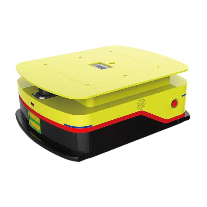
Hydraulic power unit of full electric stacker
Cat:DC series hydraulic power unit
This hydraulic power unit of full electric stacker is specially designed for full electric stacker. It is integrated by a high-pressure gear pump, a D...
See DetailsContent
A high speed low torque hydraulic motor deserves consideration only when your equipment requires high rotational speed with a relatively small load. In practical terms, that means speeds above 3000 rpm and continuous torque below 100 N·m. Before evaluating the motor itself, confirm the four values that matter most: rated speed, displacement, working pressure, and overall efficiency. A small displacement motor can run at high rpm but will generate limited torque, so the application must truly be a light-duty, fast-cycling one.
In many compact hydraulic systems, a high speed low torque motor is used to drive fans, pumps, or small conveyors. These devices are not torque-hungry but they do need fast response and smooth rotation. When you request a quote, state the actual working speed and load torque first. Suppliers can then propose a motor size and displacement that matches your flow and pressure conditions.
A hydraulic motor converts fluid pressure into rotational mechanical power. The terms high speed and low torque refer to the operating envelope of the motor. High speed motors typically operate at 3000 to 6000 rpm, while low torque means the output torque stays under roughly 120 N·m. This envelope is achieved by using a small displacement per revolution. Small displacement motors move less fluid per turn, which allows them to spin faster with a given pump flow but produces less torque.
Three common constructions are used for these motors. External gear motors are the most popular choice for light-duty high-speed applications because they have few moving parts, tolerate contamination better, and are inexpensive. Vane motors offer smoother operation and are often selected when noise is a concern. Piston motors can also run at high speed but are more expensive and are mainly chosen when high pressure and precise control are required.
The following table summarizes the typical parameter ranges and the selection impact of each value. Read this before comparing quotes from different suppliers.
| Parameter | Typical Range | Impact on Selection |
|---|---|---|
| Rated Speed | 3000–6000 rpm | Defines the pump flow needed and the achievable cycle time. |
| Displacement | 2–30 cc/rev | Higher displacement gives more torque but lowers maximum speed. |
| Rated Torque | 5–120 N·m | Never select a motor whose rated torque is lower than 1.2 times the continuous load. |
| Working Pressure | 70–210 bar | Higher pressure raises torque but also increases internal leakage and heat. |
| Overall Efficiency | 70–90% | A low-efficiency motor will waste energy and require more cooling. |
When the duty cycle is intermittent, you can sometimes use a higher pressure and smaller displacement to reach the required torque. But for continuous operation, the rated torque must be realistic and the system should have a margin for starting friction. The speed range must also be wide enough to cover both minimum and maximum operating speeds.
A high speed low torque motor is practical in equipment that prioritizes rapid movement over heavy pushing. Common cases include:
In all these cases, the torque demand stays below approximately 100 N·m and the speed demand is typically above 2000 rpm. If your application resembles one of these, a small gear motor is usually the most cost-effective solution.
If you are building a hydraulic circuit from scratch, a standalone motor is only one part of the system. You still need a hydraulic pump, a reservoir, a directional control valve, a relief valve, and a proper coupling. Each component must match the motor's flow and pressure requirements. This is where many small equipment manufacturers lose time, because a mismatch between pump flow and motor displacement causes overspeed, overheating, or poor controllability.
 Integrated brushless motor hydraulic power unit for efficient lifting controlThis compact power pack combines a high-pressure gear pump, brushless DC motor, valve block, and tank, offering reliable and efficient hydraulic drive with optional speed regulation for smooth lifting operations.View Product →
A complete hydraulic power unit solves that problem by integrating the motor, pump, tank, and valves in one pre-engineered package. For applications that need a smaller footprint and a more consistent duty cycle, a DC micro power unit or a brushless motor power unit delivers a ready-to-install solution. You simply connect the hydraulic lines and the electric controls, and the system is ready to run.
 Compact DC micro power unit for double-acting hydraulic cylindersDesigned for space-limited applications, this unit integrates a DC motor, gear pump, and solenoid valve to provide precise bidirectional control, making it suitable for mobile equipment and small machinery.View Product →
When a power unit is selected instead of a single motor, the supplier must also verify the pump flow, valve sizing, tank volume, and pressure setting. These factors determine whether the motor will actually reach the speed you expect. That is why most buyers prefer to discuss the entire power pack rather than just a motor. If you are comparing options for a compact hydraulic system, the DC hydraulic power unit guide provides further detail on model selection and common configurations.
This comparison helps you decide which motor family fits your machine. It is not a strict boundary, but a practical guideline used by most hydraulic engineers.
| Characteristic | High Speed Low Torque | Low Speed High Torque |
|---|---|---|
| Speed Range | 3000–6000 rpm | 0–500 rpm |
| Torque Output | 5–120 N·m | 500–5000 N·m |
| Displacement | 2–30 cc/rev | 50–500 cc/rev |
| Typical Load | Light and fast | Heavy and slow |
| Best Use | Fans, pumps, conveyors | Winches, slew drives, lifts |
The choice becomes obvious once you know your machine's cycle time and load profile. Fast cycles with a short stroke or light object favor the high speed low torque side. Long, heavy movements with high inertia favor the low speed high torque side.
Even experienced engineers sometimes fall into a few repeatable traps when ordering a motor for a high-speed application. Here are the five most common ones.
The safest approach is to provide the supplier with your required speed range and maximum working torque, not just a motor code. The supplier can then check whether a gear motor, a vane motor, or a piston motor offers the best balance of cost and reliability.
If your project involves an AC-powered power unit, you may also benefit from reading the AC hydraulic power unit buyer guide for more context on matching motors to electric pump packages.
High speed motors are more sensitive to oil condition than low speed units because the moving parts cycle more times per minute. The wear rate increases when the oil contains particles larger than 10 microns. A standard 25-micron filter may not be enough.
Keep the fluid temperature below 60 degrees Celsius. Above that, the oil viscosity decreases and internal leakage grows, which reduces torque and system efficiency. If your duty cycle is continuous, plan for a heat exchanger or a larger reservoir.
Check for external leaks around the shaft seal regularly. A high speed motor can quickly spin a damaged seal, allowing oil to escape and air to enter. Air in the fluid leads to cavitation, which damages the gear surfaces.
Use the oil grade recommended by the motor manufacturer. For most gear motors, ISO VG 32 or ISO VG 46 hydraulic oil works well in normal ambient temperatures.
For external gear motors, practical speeds usually reach 6000 rpm. Beyond that, cavitation risk and bearing load increase significantly. Some small vane motors are limited to around 4000 rpm. Always confirm the maximum speed from the supplier, because operating near the limit shortens service life.
Required displacement in cubic centimeters per revolution equals the required torque in N·m divided by the pressure difference in bar, multiplied by 20 times the mechanical efficiency. In short terms, a higher working pressure means a smaller displacement can achieve the same torque. This calculation helps you compare motor options before requesting a quote.
Most gear motors are bidirectional by design. However, the shaft seal and internal pressure compensations may differ. If your application requires frequent reversing, tell the supplier so they can confirm the motor can operate safely in both directions under the same pressure conditions.
A hydraulic motor is a single rotating actuator. A hydraulic power unit is a complete system that includes the motor, pump, reservoir, valves, heaters, filters, and controls. A power unit delivers ready-to-install hydraulic energy, while a motor only converts that energy into rotation.
A simple external gear motor is usually the best choice. It offers high speed capability, low cost, and good resistance to contamination. If the application demands lower noise or smoother rotation, a balanced vane motor may be worth the extra cost.
Selecting the right high speed low torque hydraulic motor is not about memorizing a catalogue. It is about defining your speed range, torque demand, and duty cycle clearly. Once those facts are fixed, the motor size, displacement, and pressure setting become straightforward.
For equipment manufacturers that prefer a complete system, a hydraulic power unit often gives better initial performance and lower installation complexity. If your project needs a custom power pack or a motor matching a specific machine, share the operating parameters with the supplier and ask for a system recommendation.

This hydraulic power unit of full electric stacker is specially designed for full electric stacker. It is integrated by a high-pressure gear pump, a D...
See Details
This hydraulic power unit is specially designed for dump trailers. It is integrated by a high-pressure gear pump, DC carbon brush machine, central val...
See Details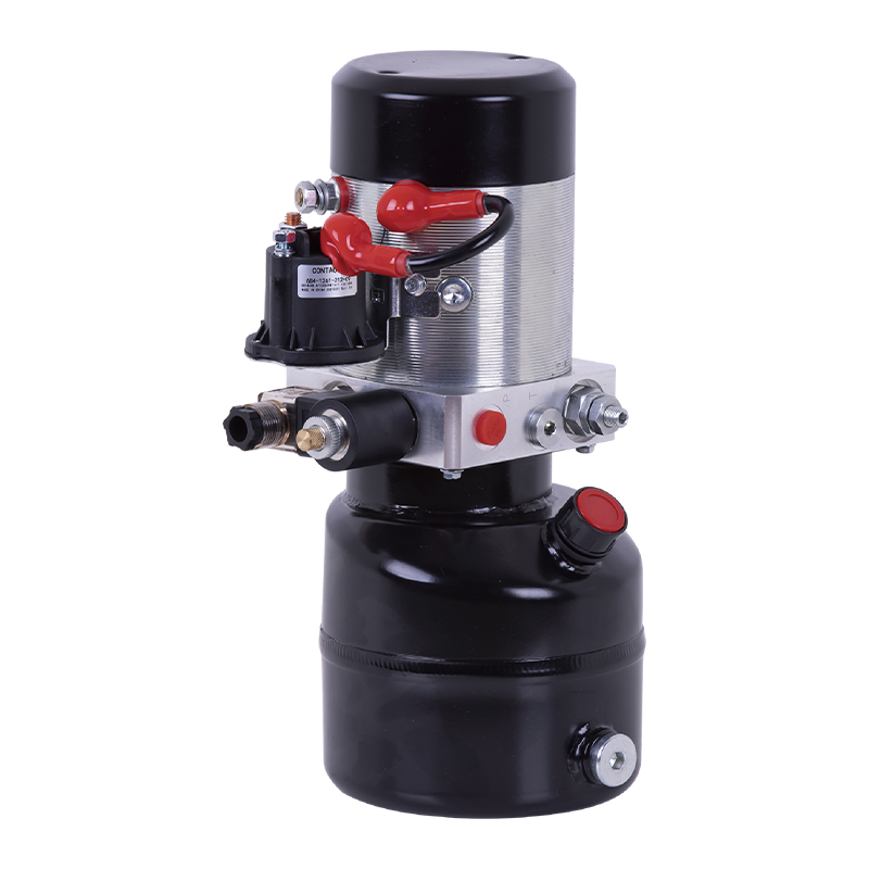
This hydraulic power unit is specially designed for a mobile hydraulic lifting table, which is integrated with a high-pressure gear pump. permanent ma...
See Details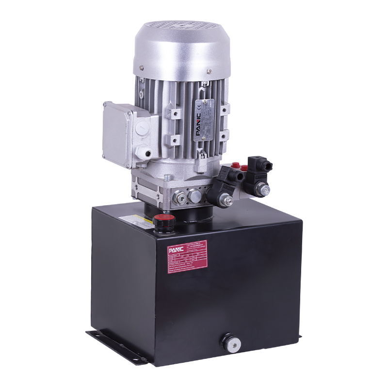
This hydraulic power unit is designed for scissor lifts and integrates a high-pressure gear pump, AC motor, center valve block, cartridge valve and oi...
See Details
This hydraulic power unit is specially designed for the clamping cylinder of the machine, too. It is integrated by a high-pressure gear pump.AC motor,...
See Details
This hydraulic power unit is specially designed for a split hydraulic lifting column, It integrates a bidirectional gear pump, AC oil-immersed motor, ...
See Details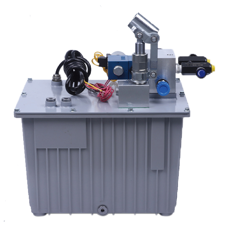
This hydraulic power unit is specially designed for an anti-terrorism hydraulic roadblock machine. It is integrated by a high-pressure gear pump, an A...
See Details
This hydraulic power unit is specially designed for hydraulic cargo elevators and is integrated with a high-pressure vane pump, AC Oil immersion motor...
See Details
ET series hydraulic lifting platform valve group is specially designed for various hydraulic lifting platforms. It can accurately control the lifting ...
See Details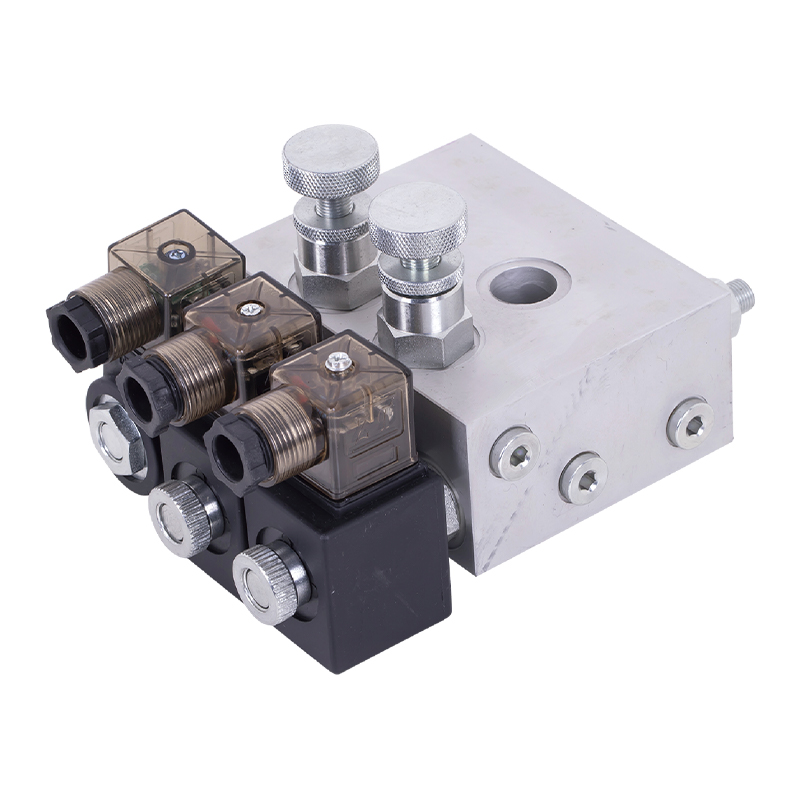
The tailgate hydraulic valve group is the core control component of the truck tailgate hydraulic system, which is designed to provide precise control ...
See Details
No. 12 Tongji Road, Simen Town, Yuyao City

+86-0574-62130352
+86-18905846028

+86-0574-62130353

Copyright© Ningbo Panic Hydraulic Technology Co., Ltd. All Rights Reserved. China Hydraulic Power Units Manufacturers

