


 English
 中文简体
中文简体 русский
Boarding axle power unit
Cat:AC series hydraulic power unit
This boarding axle power unit is specially designed for fixed boarding ramps and integrates a high-pressure gear pump, an AC motor center valve block,...
See DetailsContent
An adjustable flow control valve hydraulic is a component that lets you manually or automatically set the rate of oil flow in a hydraulic circuit. It does not simply open or close like a basic valve; it throttles the flow to a precise, repeatable value. This gives you control over actuator speed, machine cycle time, and system power consumption. The most common applications are speed control of cylinders, motors, and hydraulic power unit output. Without this valve, a hydraulic actuator would move at whatever speed the pump delivers, which is almost never what the process needs.
For hydraulic power unit manufacturers like Ningbo Panic Hydraulic Technology, the adjustable flow control valve is not an optional luxury. It is the difference between a machine that performs consistently and one that constantly needs operator intervention. A properly sized valve keeps a lift platform smooth, a tailgate steady, and a stacker truck predictable. As of 2026, the most advanced adjustable flow control valves offer repeatability within 1% to 2% of set flow, which is critical when multiple actuators must synchronize.
Flow control is the primary lever for adjusting how fast a hydraulic cylinder extends or retracts. The relationship is simple: flow rate (in liters per minute) divided by cylinder area gives the speed (in meters per minute). If you change the flow by 20%, you change the speed by 20%. That matters in real applications. For example, a hydraulic tailboard power unit that lifts a truck's tailgate must move smoothly and stop at the exact end position. If the flow control valve drifts or gets clogged, the tailgate may jerk, slam, or fail to reach its stop. A similar problem occurs with large shear lifting power units, where uneven flow between two cylinders causes the platform to tilt.
Beyond speed, flow control affects pressure losses and heat generation. Every time you restrict flow, you convert pressure energy into heat. The more inefficient the throttle, the hotter the oil becomes. An excessively hot hydraulic system (above 55°C / 131°F) accelerates pump wear, degrades seals, and shortens fluid life. A well-designed adjustable flow control valve minimizes pressure drop when the setting is fully open, while still providing the needed restriction when the setting is reduced. That is why valve geometry, not just the adjustment knob, determines system efficiency.
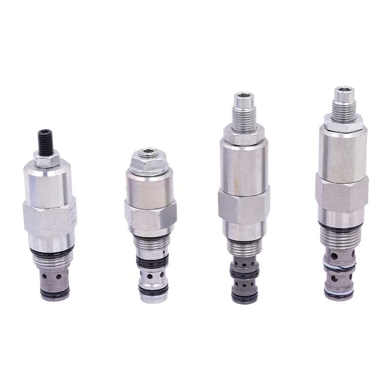 Adjustable Regulating Valve for Hydraulic Flow and Pressure ControlThis regulating valve precisely adjusts fluid flow, pressure, and temperature in industrial systems. It responds quickly to control signals, ensuring stable operation and helping manage heat generation in hydraulic circuits.View Product →
Not all adjustable flow control valves behave the same way. The choice depends on whether your circuit needs simple throttling, pressure compensation, or proportional electronic control. Below is a practical breakdown of the four most common types used in hydraulic power units and mobile equipment.
Choosing the wrong valve can lead to sluggish actuators, overheating, or premature failure. Here are the six parameters you must evaluate before buying. I have seen buyers focus only on the port size, but that is a mistake. The following factors determine real-world performance.
| Parameter | What to check | Typical value |
|---|---|---|
| Nominal flow range | Minimum and maximum adjustable flow at the max pressure | 0.5 to 60 L/min |
| Maximum operating pressure | Peak pressure the valve body, seals, and springs can withstand | 210 to 350 bar |
| Flow regulation accuracy | How much flow varies for a given knob position under load change | ±1% to ±5% |
| Adjustment type | Manual screw, lockable knob, or electronic proportional | Manual or proportional |
| Leakage rate | Internal leakage when the valve is fully closed or at rest | less than 0.5 mL/min |
| Mounting and port size | Line mount, subplate, or cartridge; BSP, NPT, or SAE ports | SAE 6 to SAE 12 |
It is important to note that the pressure drop at the chosen flow setting directly affects the required pump size. If you select a valve that is too small, the flow will be limited even when fully open, and the pump will run at a higher pressure than intended, wasting energy. If you select a valve that is too large, the adjustment range becomes very sensitive, and the finest adjustments get difficult to make. A practical rule is to choose a valve whose nominal flow rating is 20% to 30% above your required flow.
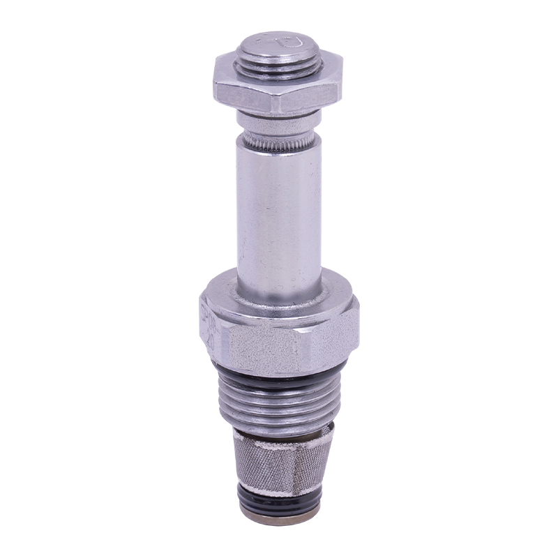 Proportional Valve for Precise Flow and Pressure RegulationThis proportional valve offers continuous, precise control of flow or pressure, responding linearly to electrical signals. Its built-in feedback ensures accurate performance, ideal for smooth speed regulation and energy-efficient hydraulic systems.View Product →
In a complete hydraulic power unit, the flow control valve is usually mounted on the valve manifold, either directly in the pump output line or within the actuator circuit. The power unit produces flow from a gear pump, then the flow control valve divides or restricts that flow before it reaches the cylinder or motor. For example, in an AC hydraulic power unit used for a lifting platform, a pressure-compensated adjustable flow control valve can be placed between the pump and the check valve to set the lift speed. When the platform must descend at a controlled rate, a separate flow control valve in the return line governs the lowering speed. This dual-valve arrangement is common in DC bidirectional pump power units, where the same pump must drive both directions.
A properly integrated flow control valve also protects the system from thermal overload. If a machine is required to run continuously, like a parking garage silent power unit, the valve must be sized so that the pressure drop does not generate excessive heat. As of 2026, energy-saving hydraulic power units often use proportional flow control valves with load sensing, reducing energy consumption by up to 30% compared to a standard constant-flow system, according to a guide on the working principle of hydraulic systems.
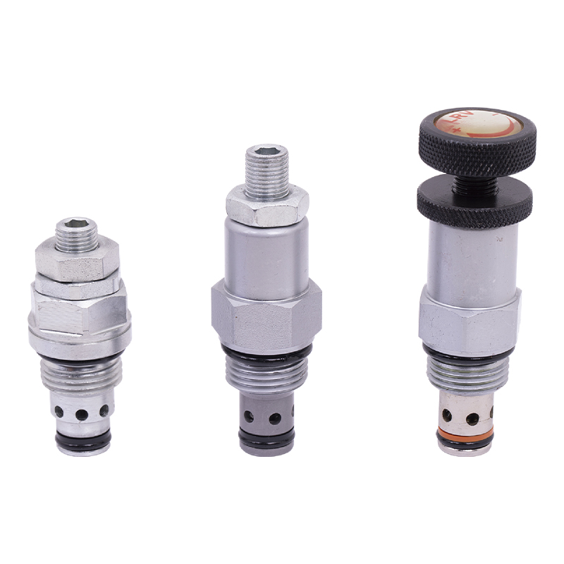 Relief Valve for Pressure Protection and System SafetyThis relief valve maintains system pressure within safe limits, automatically opening when pressure exceeds the set value. It prevents equipment damage and supports thermal management, making it vital for reliable hydraulic operation.View Product →
Flow control valves are relatively simple, but they fail in predictable ways. The most common issue is contamination buildup. When tiny particles (3 to 5 microns) pass through the restrictive orifice, they can lodge in the throttle gap. The result is inconsistent flow, even if the adjustment knob is not moved. Another frequent failure is spring fatigue in pressure-compensated models. If the spring weakens, the compensating spool opens or closes too early, causing flow to vary as load changes. The table below lists symptoms, probable causes, and recommended checks.
| Symptom | Probable cause | Action |
|---|---|---|
| Actuator speed changes with load | No pressure compensation, or damaged compensating spring | Replace with a pressure-compensated valve; check spring length and preload |
| Flow stops completely after some time | Contaminant pushed into the valve and wedged the spool | Clean valve, upgrade filtration to at least 10 microns absolute |
| Valve makes whistling or buzzing noise | Cavitation or aeration due to high vacuum or air in the oil | Check suction line for leaks; bleed the system; verify tank level |
| Oil temperature rises quickly | Excessive pressure drop across the valve | Select a larger valve or reduce pump flow; add a cooling circuit |
| Adjustment knob becomes stiff | External debris on the knob thread or internal corrosion | Clean knob, apply thin coat of anti-seize; inspect rod for scoring |
One of the best ways to prevent these failures is to keep the hydraulic fluid clean. According to a 2023 industry survey on hydraulic system reliability, more than 75% of premature valve failures are caused by contaminated oil. That is why a high-quality suction filter and return-line filter are essential for any power unit that uses an adjustable flow control valve.
Adjustable flow control valves need periodic attention, but not excessive maintenance. The key is to establish a routine that checks the valve without dismantling the whole system. First, record the initial flow setting in liters per minute and mark the knob position. After every 500 operating hours, compare the valve's flow output with that reference. If the deviation is more than 5%, plan a cleaning or replacement. Second, inspect the valve's adjustment mechanism for stiffness or free play. A loose knob means the set point has drifted, which can cause serious safety issues on a hydraulic lifting column.
For proportional flow control valves, calibration is usually done through the electronic controller. You will need to set the minimum and maximum current signals that correspond to the desired flow range. It is a good practice to perform the calibration at a known oil temperature, ideally 40°C, because viscosity changes with temperature. If the system works in a wide temperature range, a temperature-compensated flow control valve is a wise investment. These valves automatically adjust the orifice area to maintain constant flow despite viscosity changes. They are particularly useful for outdoor mobile equipment that faces colder mornings and hot afternoons.
When you are sourcing a valve for a hydraulic power unit, do not simply compare prices. The following questions will help you avoid costly mistakes.
A supplier that manufactures its own valve blocks and integrates the flow control valve into the manifold is often a better choice than a merchant that only sells packaged parts. The ability to test the complete manifold before shipping reduces installation time and eliminates hidden leaks. For a hydraulic power unit manufacturer, this integration capability is a strategic advantage, because they can guarantee that the valve performs exactly as specified in the system diagram.
A flow control valve regulates the volume of oil passing through it per unit time. A pressure control valve, such as a relief valve, regulates the pressure in a circuit by diverting excess flow. While they are different, they are often used together. For example, an Relief Valve for Pressure Protection and System SafetyThis relief valve maintains system pressure within safe limits, automatically opening when pressure exceeds the set value. It prevents equipment damage and supports thermal management, making it vital for reliable hydraulic operation.View Product → can protect a flow control valve from overpressure.
Yes, but only in low-precision applications. A needle valve is a non-compensated flow control. If the load on the actuator changes, the flow will change. In a hydraulic power unit that sees varying loads, a pressure-compensated or proportional valve is strongly recommended.
If the system only needs 5 L/min but you install a valve rated at 20 L/min, turning the knob a tiny amount changes the flow dramatically. You will find it hard to make fine adjustments. A good rule is to choose a valve with a rated flow no more than 2 to 3 times your actual flow requirement.
For most applications, it is safer to control the flow on the outlet (meter-out) side of a cylinder. This creates a back pressure that prevents the actuator from running away when the load is pulling downhill. In a hydraulic power unit, this can be done with a manifold block that contains a meter-out flow control.
Start with the adjustment fully closed, then slowly open it while monitoring the actuator speed with a timer or flow meter. Note the position that gives the desired stroke time. Lock the knob in place, and record the flow setting on the unit's nameplate. This simple practice avoids careless mistakes and speeds up future troubleshooting.
Heat is generated when the oil is forced through a restriction. If the valve is too small or the set point is too close to the closed position, the pressure drop is enormous, converting almost all the pump output into heat. Check the pressure gauge before and after the valve. If the difference is more than 50 bar, you are wasting energy. Either increase the valve size or reduce the pump flow.
An adjustable flow control valve is a small component, but it has a large impact on how well a hydraulic system performs. Choosing the right type, sizing it correctly, and maintaining it will save you from downtime, repair costs, and operator frustration. Whether you are building a mobile lifting platform power unit or a silent hydraulic cargo elevator, the time you spend on flow control selection pays off in every cycle.
As a buyer, you should look for a supplier that can show you flow curves, pressure drop data, and contamination tolerance. A manufacturer that understands both the valve and the power unit as a whole will help you create a machine that runs smoothly for years. In 2026, the trend is clearly toward smarter, more efficient hydraulic systems. An adjustable flow control valve that is properly applied is one of the most cost-effective upgrades you can make.

This boarding axle power unit is specially designed for fixed boarding ramps and integrates a high-pressure gear pump, an AC motor center valve block,...
See Details
Designed for hydraulic lifting platforms, this lifting platform power unit integrates a high-pressure gear pump, AC motor, center valve block, cartrid...
See Details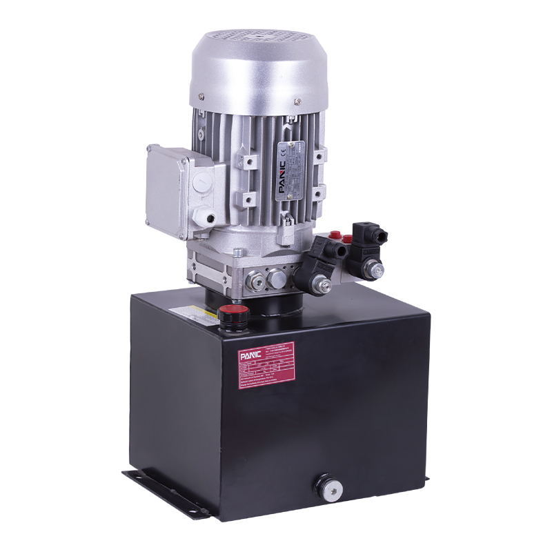
This hydraulic power unit is designed for scissor lifts and integrates a high-pressure gear pump, AC motor, center valve block, cartridge valve and oi...
See Details
This hydraulic power unit is specially designed for the clamping cylinder of the machine, too. It is integrated by a high-pressure gear pump.AC motor,...
See Details
This hydraulic power unit is designed specifically for CNC machine tool cutting cylinders and can provide precise power and control, consisting of a h...
See Details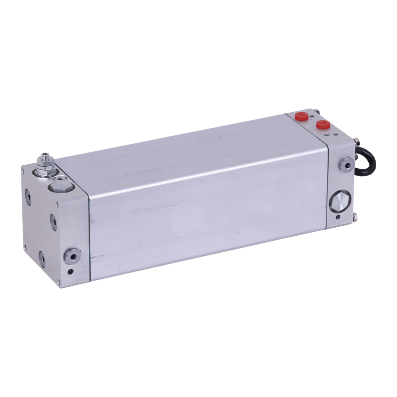
This oil immersed bidirectional pump power unit is designed for various types of mechanical equipment. It integrates a high-pressure bidirectional gea...
See Details
This hydraulic power unit is specially designed for hydraulic cargo elevators and is integrated with a high-pressure vane pump, AC Oil immersion motor...
See Details
ET series hydraulic lifting platform valve group is specially designed for various hydraulic lifting platforms. It can accurately control the lifting ...
See Details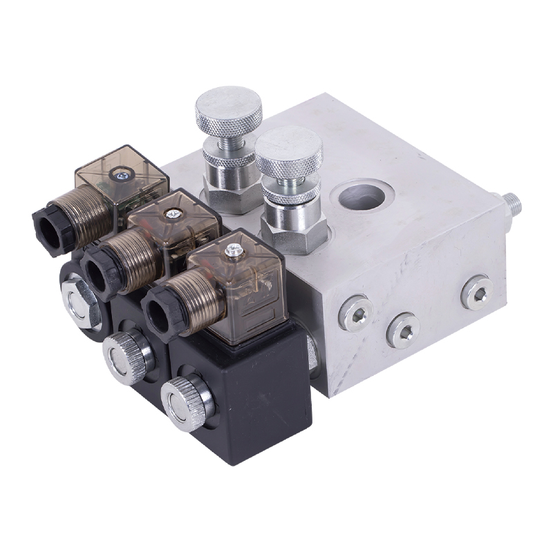
The tailgate hydraulic valve group is the core control component of the truck tailgate hydraulic system, which is designed to provide precise control ...
See Details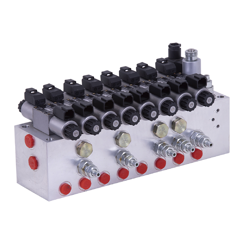
The modular hydraulic valve block uses modular integrated design to accurately combine multiple hydraulic valves, greatly simplifying the system pipel...
See Details
No. 12 Tongji Road, Simen Town, Yuyao City

+86-0574-62130352
+86-18905846028

+86-0574-62130353

Copyright© Ningbo Panic Hydraulic Technology Co., Ltd. All Rights Reserved. China Hydraulic Power Units Manufacturers

