
 English
 中文简体
中文简体 русский
Hydraulic tailboard power unit
Cat:DC series hydraulic power unit
This hydraulic power unit is specially designed for the hydraulic tail plate. The vehicle tail plate hydraulic power unit is a power unit used for the...
See DetailsContent
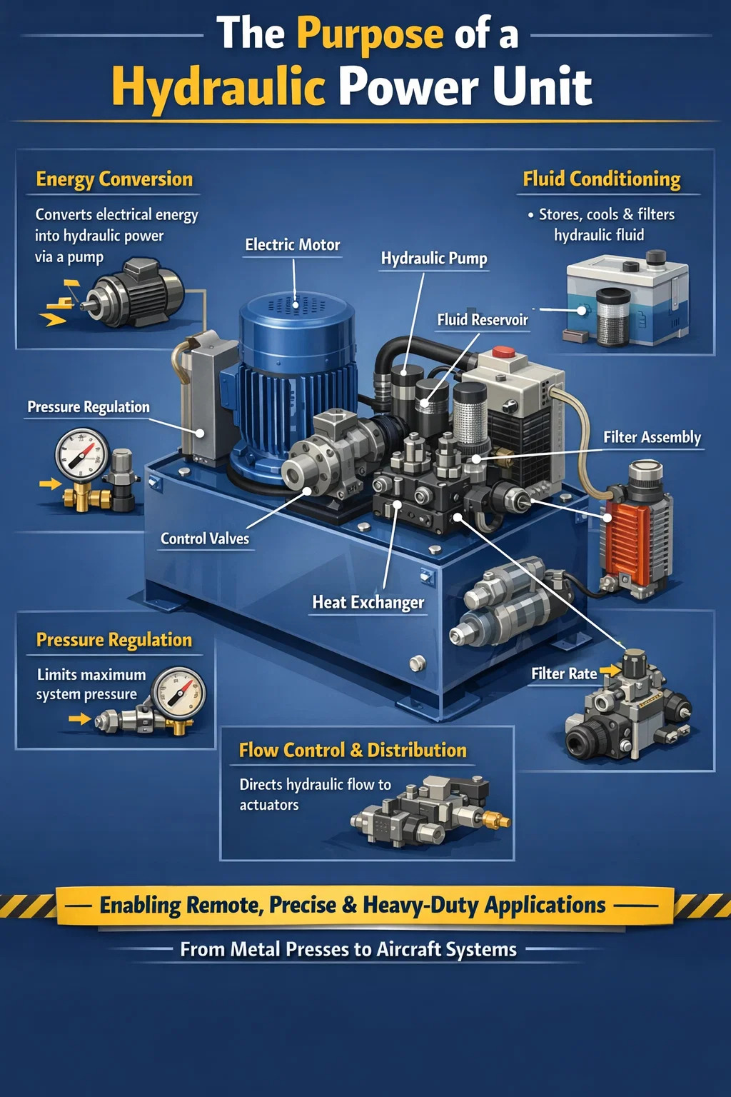
A hydraulic power unit (HPU) exists for one fundamental purpose: to convert electrical or mechanical energy into controlled hydraulic power — pressurized fluid — that can be transmitted, directed, and used to do useful mechanical work at a distance. It is the central energy source of any hydraulic system, generating the flow and pressure that actuators, motors, and cylinders need to move loads, hold positions, or apply forces that would be impractical or impossible with purely mechanical or electrical means.
In practical terms, a hydraulic power unit takes in electrical power from a motor, uses a pump to pressurize hydraulic fluid, and delivers that fluid through control valves to wherever work needs to be done — whether that is lifting a 500-ton press, steering a construction excavator, clamping a machined part, or extending the landing gear of a commercial aircraft. The HPU does not perform the work itself; it provides the power and control infrastructure that makes the work possible.
Without a hydraulic power unit, the actuators, cylinders, and hydraulic motors in a system would have no energy source. The HPU is to a hydraulic circuit what a power supply is to an electronic system — it defines the available power envelope, sets the operating pressure range, and determines how quickly and accurately the system can respond.
The purpose of a hydraulic power unit can be broken down into several distinct functional roles that it performs simultaneously within any hydraulic system.
The primary job of the HPU is energy conversion. An electric motor — typically rated anywhere from 0.5 kW for small bench units to over 1,000 kW for large industrial systems — drives a hydraulic pump. The pump converts the rotational mechanical energy of the motor into hydraulic energy in the form of flow at pressure. This energy can then be transported through hoses and pipes over considerable distances and converted back into mechanical work wherever needed.
The reservoir integrated into the hydraulic power unit stores the working fluid — typically between 10 and 2,000 liters depending on system size — and allows it to cool, deaerate, and settle before re-entering the pump. The HPU also houses the filtration system that keeps the fluid clean, and often a heat exchanger to maintain optimal fluid temperature. This conditioning role is critical: fluid cleanliness and temperature directly affect the service life of every downstream component.
The HPU contains a pressure relief valve that caps maximum system pressure, preventing overload damage to the pump, valves, actuators, and piping. In most industrial hydraulic systems, this maximum pressure is set between 150 and 350 bar, though high-pressure systems in aerospace, testing, and specialty applications can exceed 700 bar. The pressure regulation function ensures that the system cannot exceed its design limits regardless of what the downstream circuit demands.
Modern hydraulic power units incorporate directional control valves, proportional valves, or servo valves that distribute pressurized fluid to specific actuators in specific sequences and at controlled flow rates. This control function determines the speed, force, and direction of every motion in the system. A single HPU can simultaneously supply multiple circuits, each with independent pressure and flow requirements, using manifold blocks and valve assemblies mounted directly on the unit.
The purpose of a hydraulic power unit becomes clearer when you understand why hydraulics is chosen over electric actuators, pneumatics, or purely mechanical drives for specific applications. Each technology has its domain, and hydraulics — specifically the HPU-driven system — dominates wherever high force density, precise control, and reliability under heavy load are simultaneously required.
Hydraulic systems generate forces that are difficult or impractical to match with electric motors at comparable size and weight. A hydraulic cylinder with a 100 mm bore operating at 250 bar produces approximately 196 kN (about 20 tonnes) of force from a component weighing a few kilograms. An electric linear actuator producing the same force would be substantially heavier and larger. This force density is why hydraulic power units are standard in applications like metal presses, injection molding machines, and heavy construction equipment.
A hydraulic cylinder with a blocked port holds its load indefinitely without consuming energy, because incompressible fluid cannot escape through a closed valve. This capability is essential in applications like clamping fixtures, lifting platforms, and hydraulic jacks that must hold a load for extended periods. An electric servo motor holding the same load would require continuous current — generating heat and consuming power even when stationary.
The pressure relief valve in a hydraulic power unit provides inherent overload protection. If the system encounters a load that exceeds the set pressure, the relief valve opens and the actuator simply stalls — no component is damaged. Electric motors and mechanical drives typically require more complex protection schemes to achieve the same level of fault tolerance.
One HPU can power actuators located many meters away through flexible hoses, making it possible to place the power source in a convenient, protected location while actuators operate in harsh, inaccessible, or explosion-risk environments. In offshore drilling rigs, for example, a single hydraulic power unit on the main deck may control valves and actuators on the seabed hundreds of meters below the surface through long umbilical hoses.
The hydraulic power unit is one of the most universally applied pieces of industrial equipment across virtually every sector that involves heavy machinery, precision motion, or large force generation. Understanding where HPUs are deployed clarifies why their purpose is so broadly relevant.
| Industry | Typical HPU Application | Key Requirement Served |
|---|---|---|
| Metal Forming & Stamping | Hydraulic presses, forging machines | Very high force, precise stroke control |
| Plastics Manufacturing | Injection molding machines | High clamp force, fast cycle times |
| Construction Equipment | Excavators, cranes, bulldozers | Multi-axis motion, rugged reliability |
| Aerospace | Landing gear, flight control surfaces | Compact, high pressure, high reliability |
| Oil & Gas | BOP control, wellhead valves, subsea systems | Remote operation, fail-safe behavior |
| Marine & Offshore | Deck cranes, anchor winches, thrusters | High power, saltwater environment tolerance |
| Steel & Mining | Rolling mill clamps, ore crushers | Extreme load capacity, continuous duty |
| Automotive Manufacturing | Welding fixture clamps, transfer press lines | Repeatability, high cycle rate |
| Agriculture | Tractor implement control, combine harvesters | Multiple simultaneous functions, field durability |
| Civil Infrastructure | Flood gates, dam sluice valves, bridge lifts | Long-term reliability, large actuator forces |
The hydraulic power unit achieves its purpose through a carefully integrated set of components. Each has a specific role, and understanding them helps clarify why the HPU is designed the way it is.
The motor provides the prime mover energy. Most industrial HPUs use three-phase AC induction motors for their reliability, simplicity, and availability in a wide power range. The motor's output shaft couples directly to the pump. Motor size determines the maximum hydraulic power the unit can deliver. In energy-efficient modern designs, a variable-speed drive controls the motor to match output to real-time demand, significantly reducing energy waste at partial loads.
The pump is the heart of the hydraulic power unit. It draws fluid from the reservoir and pushes it into the system circuit under pressure. Gear pumps are used in lower-pressure, cost-sensitive applications. Vane pumps provide quieter operation. Piston pumps — both axial and radial types — are used in high-pressure, high-efficiency, or variable-displacement applications. Pump displacement is specified in cubic centimeters per revolution (cc/rev), and at a given shaft speed, this directly determines the flow rate the HPU can supply.
The reservoir stores hydraulic fluid and serves multiple secondary purposes: it allows air bubbles to escape, provides a thermal buffer to absorb heat from the system, and gives particulate contamination time to settle before fluid recirculates. The standard rule of thumb is to size the reservoir at 3 to 5 times the pump flow rate per minute, though high-heat applications may require larger tanks or supplementary cooling.
This valve is the system's primary safety device. It opens automatically when pressure exceeds the preset limit, diverting excess flow back to the reservoir. Without it, a blocked actuator or stalled cylinder would cause pressure to climb until a pipe, hose, or component fails. The relief valve is not a control component — it is a protection device — and a properly designed HPU should rarely activate it during normal operation.
Hydraulic fluid cleanliness is one of the most critical factors in system longevity. Filters in the HPU — typically on the return line, the pressure line, or both — remove particulate contamination before it can damage pump internals, valve spools, and cylinder seals. Most industrial HPUs target a fluid cleanliness level of ISO 4406 class 16/14/11 to 18/16/13, using filters with ratings of 3–10 microns absolute.
Energy losses in the hydraulic system manifest as heat in the fluid. Without a heat exchanger, fluid temperature would rise continuously until seals degrade, viscosity drops, and component wear accelerates. Air-blast or water-cooled heat exchangers are sized to dissipate the expected heat load — typically 25% to 40% of input power in a conventional fixed-pump circuit — and maintain fluid temperature between 40°C and 60°C.
Directional control valves, proportional valves, pressure-reducing valves, and flow control valves are often mounted on a manifold block integrated into the HPU. These components route pressurized fluid to the correct actuator at the correct pressure and flow rate on command from a PLC, manual control, or automatic sequence controller. The manifold-mounted approach reduces pipe connections, minimizes leak points, and keeps the system compact.
Beyond brute force applications, the hydraulic power unit serves a precision purpose in automated manufacturing and process control. With proportional or servo valve technology, HPU-driven systems can control actuator position to within ±0.01 mm and force to within 1% of set point — performance levels that make hydraulics competitive with electric servo drives in many force-intensive applications.
In a modern servo-hydraulic system, a closed-loop controller continuously compares the actual actuator position (measured by a linear transducer) with the commanded position and adjusts the servo valve opening accordingly, correcting for load disturbances and flow variations in real time. This closed-loop capability is used in:
In every one of these applications, the hydraulic power unit is what makes the force and motion possible. The servo valve and controller determine precision; the HPU determines power capacity.
The way a hydraulic power unit is deployed within a facility or machine depends on the specific purpose it needs to serve. There are two fundamental architectural approaches, each suited to different requirements.
A single large HPU serves multiple machines or workstations through a ring main or branched distribution system. This approach is used in large manufacturing plants where many machines need hydraulic power simultaneously. The advantage is that one unit, one set of controls, and one maintenance point serve the whole facility. A centralized HPU for an automotive body shop might be rated at 500 kW or more, supplying dozens of welding and clamping stations. The trade-off is that a failure affects all downstream machines simultaneously, and long pipe runs introduce pressure losses.
Each machine or process cell has its own dedicated HPU, sized specifically for that machine's requirements. This is the more common arrangement in modern manufacturing because it provides independence — one machine's HPU failure does not affect others — and allows each unit to be optimized for its specific duty cycle and pressure requirements. Compact HPUs in this category range from 0.5 kW bench-top units for small test fixtures up to 200+ kW units for large injection molding or die casting machines.
Portable HPUs serve a specific purpose in maintenance, construction, and emergency response: providing on-demand hydraulic power where no fixed installation exists. Hydraulic rescue tools (the "jaws of life") are powered by portable HPUs. Pipeline construction crews use portable units to drive hydraulic pipe benders and crimpers. Maintenance teams use them to operate hydraulic torque wrenches on large flanged joints where power is unavailable. These units are typically diesel or gasoline engine-driven rather than electric, allowing operation in remote or off-grid locations.
In safety-critical applications, the hydraulic power unit serves a purpose that goes beyond simply driving motion — it must provide guaranteed, fail-safe operation under fault conditions. This is particularly important in three areas.
Hydraulic power units in oil and gas facilities drive emergency shutdown (ESD) valves and blowout preventer (BOP) systems. These HPUs must be able to actuate large valves quickly and reliably under fault conditions — including during power failures. Accumulator banks charged by the HPU store sufficient hydraulic energy to operate all emergency valves multiple times even if the primary power source is lost. In offshore installations, BOP control HPUs are designed to API 16D or equivalent standards with full redundancy.
Commercial aircraft carry multiple independent hydraulic power units — typically two or three systems, each with its own pump (engine-driven, electric, or air-driven), reservoir, and circuit — so that a failure in one system does not compromise flight control. The Boeing 737, for example, has two independent hydraulic systems, each capable of operating primary flight controls independently. The purpose of each HPU in this context is as much about redundancy and failure tolerance as it is about power generation.
Hydraulic press brakes and shearing machines use HPUs to drive rams with forces that could cause serious injury if uncontrolled. The HPU in these machines incorporates counterbalance valves, dual-channel safety valve systems, and position monitoring to ensure the ram can only move at controlled speeds and cannot free-fall in the event of a hose failure or valve fault. The safety control function of the HPU is as important as its power delivery function.
Selecting a hydraulic power unit for a given purpose requires matching the unit's specifications to the demands of the application. The key parameters that define what an HPU needs to deliver are:
Getting this specification right is fundamental to the HPU fulfilling its purpose reliably. An undersized unit will overheat and fail prematurely. An oversized unit wastes energy and capital. Proper engineering of the HPU specification is the foundation of a successful hydraulic system.
The purpose of the hydraulic power unit has remained constant — convert and deliver controlled hydraulic power — but the way that purpose is fulfilled has evolved significantly with advances in electronics, materials, and fluid technology.
Modern HPUs increasingly incorporate IoT-enabled sensors that continuously monitor fluid temperature, pressure, pump flow output, filter differential pressure, and motor current draw. This data feeds into predictive maintenance algorithms that can detect developing pump wear, filter blockage, or fluid contamination weeks before they cause a failure. A plant with 50 HPUs networked to a central monitoring system can achieve 40–60% reductions in unplanned downtime compared to time-based maintenance schedules.
Electro-hydraulic actuators (EHAs) — self-contained units combining a small electric motor, pump, and actuator in a single package — are beginning to replace conventional HPU-fed circuits in some applications, particularly in aerospace and mobile machinery where weight and installation space are at a premium. However, for high-power, multi-actuator, or continuous-duty industrial applications, the centralized hydraulic power unit remains the most practical and cost-effective solution and is expected to remain so for the foreseeable future.
The introduction of water-glycol, synthetic ester, and fire-resistant hydraulic fluids has also expanded the environments in which HPUs can safely operate — particularly in foundries, die casting facilities, and underground mining where fire risk makes mineral oil unsuitable. In these settings, the HPU serves the same fundamental purpose but with a fluid specification chosen to meet safety regulations without sacrificing performance.

This hydraulic power unit is specially designed for the hydraulic tail plate. The vehicle tail plate hydraulic power unit is a power unit used for the...
See Details
This hydraulic pump station is composed of a series of side inlet and side outlet gear pumps and 4.5 or 5-inch DC motors. It is often used as a hydrau...
See Details
This DC bidirectional pump power unit adopts an integrated design of multiple components such as a bidirectional gear pump, a permanent magnet DC moto...
See Details
This hydraulic power unit is designed for scissor lifts and integrates a high-pressure gear pump, AC motor, center valve block, cartridge valve and oi...
See Details
This hydraulic power unit is specially designed for a double-acting oil cylinder system, which is integrated by a high-pressure gear pump, an AC motor...
See Details
This oil immersed bidirectional pump power unit is designed for various types of mechanical equipment. It integrates a high-pressure bidirectional gea...
See Details
This hydraulic power unit is specially designed for the three-dimensional parking garage and is integrated by a high-pressure vanepump, an AC oil imme...
See Details
The V3068 hydraulic valve group is an electric check valve group designed for hydraulic systems. It is mainly used to prevent the backflow of media, e...
See Details
The modular hydraulic valve block uses modular integrated design to accurately combine multiple hydraulic valves, greatly simplifying the system pipel...
See Details
The relief valve is the core component for controlling pressure in the hydraulic system. It can maintain the stability of the system pressure and prev...
See Details
No. 12 Tongji Road, Simen Town, Yuyao City

+86-0574-62130352
+86-18905846028

+86-0574-62130353

Copyright© Ningbo Panic Hydraulic Technology Co., Ltd. All Rights Reserved. China Hydraulic Power Units Manufacturers
