
 English
 中文简体
中文简体 русский
Hydraulic tailboard power unit
Cat:DC series hydraulic power unit
This hydraulic power unit is specially designed for the hydraulic tail plate. The vehicle tail plate hydraulic power unit is a power unit used for the...
See DetailsContent
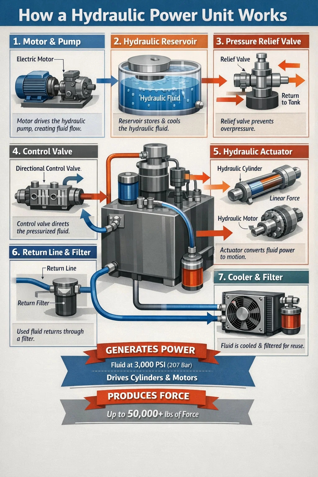
A hydraulic power unit (HPU) works by using an electric motor or combustion engine to drive a hydraulic pump, which draws fluid from a reservoir and pressurizes it. That pressurized fluid is then directed through control valves to actuators — cylinders or hydraulic motors — which convert the fluid energy into mechanical force or motion. Once the fluid completes its work, it returns to the reservoir, where it is filtered and cooled before the cycle repeats.
This closed-loop process allows a compact unit to generate enormous force. A standard industrial HPU operating at 3,000 PSI (207 bar) can deliver tens of thousands of pounds of pushing or pulling force through a relatively small cylinder, which is why hydraulic systems remain the dominant choice in heavy equipment, manufacturing presses, aerospace ground support, and marine applications.
Understanding how a hydraulic power unit works starts with knowing what each major component does. Every HPU — from a 1-gallon bench-top unit to a 500-gallon industrial power pack — contains the same fundamental building blocks.
The reservoir stores the hydraulic fluid supply. It is not simply a passive container. A well-designed reservoir allows entrained air to escape from returning fluid, provides enough surface area for heat dissipation, and uses internal baffles to separate the return line from the pump suction inlet. This separation prevents hot, aerated return fluid from immediately re-entering the pump. Tank sizing rules of thumb suggest a fluid volume equal to three to five times the pump's per-minute flow rate, though high-duty-cycle systems often require more.
The prime mover supplies the mechanical energy that drives the pump. In industrial and stationary applications, a three-phase AC electric motor is standard, typically ranging from 1 HP for small shop presses to over 200 HP for large hydraulic press lines or injection molding machines. Mobile equipment — excavators, skid steers, cranes — uses the vehicle's diesel engine as the prime mover, with a power take-off (PTO) connecting it to the hydraulic pump.
The pump is the heart of the hydraulic power unit. It does not create pressure — it creates flow. Pressure only develops when that flow meets resistance (a load). Three pump types dominate:
Control valves govern where fluid goes, how fast it moves, and how much pressure is allowed. The three main categories are:
Actuators are the output devices that convert hydraulic fluid power back into mechanical work. Hydraulic cylinders produce linear force and motion — extending or retracting a rod. Hydraulic motors produce rotary motion and torque. The choice depends entirely on what kind of movement the application requires.
Contamination is the number-one cause of hydraulic component failure — industry surveys consistently attribute 70–80% of hydraulic failures to fluid contamination. Filters are positioned at suction (to protect the pump), pressure (to protect downstream components), and return (to clean fluid before it re-enters the reservoir). Filter ratings are expressed in microns; most systems target a cleanliness level of ISO 4406 Class 16/14/11 or better.
Hydraulic systems generate heat — roughly 25–30% of input power is typically lost as heat in a standard system. Fluid operating above 180°F (82°C) degrades rapidly, accelerating seal wear and oxidation. Air-blast coolers or water-cooled heat exchangers maintain fluid temperature within the recommended operating range, typically 100°F to 140°F (38°C to 60°C).
Breaking down the operating cycle makes it clear exactly how a hydraulic power unit works from start to finish:
Not all hydraulic power units work the same way internally. Design choices significantly affect performance, efficiency, and application suitability.
| HPU Type | Pump Type | Typical Pressure Range | Best Application | Efficiency |
|---|---|---|---|---|
| Fixed displacement, fixed speed | Gear pump | Up to 3,000 PSI | Log splitters, dump trailers, simple lifts | Low (constant bypass losses) |
| Fixed displacement, fixed speed | Vane pump | Up to 2,500 PSI | Machine tools, low-noise environments | Moderate |
| Variable displacement | Axial piston pump | Up to 6,000+ PSI | Presses, injection molding, aerospace | High (output matches demand) |
| Variable speed drive (VSD) HPU | Fixed displacement piston or gear | Up to 5,000 PSI | Energy-sensitive industrial applications | Very high (motor speed varies with demand) |
| Air-driven HPU | Air-hydraulic intensifier | Up to 10,000+ PSI | Portable clamping, aircraft maintenance | Low flow, very high pressure |
In a variable displacement HPU, the pump automatically adjusts its output flow to match system demand. When an actuator is holding position and no movement is needed, the pump destokes and delivers only enough flow to maintain pressure. This dramatically reduces heat generation and energy consumption compared to fixed-displacement systems that continuously bypass excess flow over the relief valve. Well-implemented variable displacement systems can cut energy consumption by 30–50% versus comparable fixed-displacement designs.
Rather than varying pump displacement, a VSD hydraulic power unit varies the motor speed via a variable frequency drive (VFD). When demand drops, the motor slows down instead of the pump bypassing flow. These systems are increasingly popular in modern industrial facilities because they reduce both energy costs and noise levels — a VSD-driven HPU at idle can operate at below 65 dB(A), compared to 75–80 dB(A) for a conventional unit at full speed.
Hydraulic fluid does far more than transmit pressure. It lubricates every internal pump and motor component, carries heat away from friction points, prevents corrosion, and seals clearances between moving parts. Selecting and maintaining the right fluid is as important as selecting the right pump.
Viscosity is the single most important fluid property in a hydraulic system. ISO VG 46 mineral oil is the most common choice for industrial HPUs operating in normal temperature environments. Viscosity that is too low causes increased internal pump leakage and accelerated wear. Viscosity that is too high increases resistance, generates more heat, and can starve the pump on cold starts. Most systems specify a viscosity range of 25–54 cSt at operating temperature.
The reason hydraulic power units are used across so many industries comes down to one core advantage: no other technology delivers comparable force density at the same cost. A 10 HP hydraulic power unit can generate over 50,000 lbf of force through a modest cylinder. An electric linear actuator of equivalent force capacity would cost several times more and occupy far more space.
Hydraulic press machines are the backbone of metal stamping, forging, and forming. A 500-ton hydraulic press uses an HPU delivering flow at 3,000–5,000 PSI to develop the tonnage needed to form steel components. Injection molding machines use HPUs to generate the clamping force — commonly 100 to 6,000 tons — that holds mold halves together during plastic injection.
Every excavator, bulldozer, and crane relies on hydraulic power. A mid-size excavator (20-ton class) typically carries an HPU delivering 50–80 gallons per minute at 5,000 PSI to power boom, arm, bucket, and swing functions simultaneously. The compact package of an HPU allows all of this power to be packaged within the machine's swing frame.
Commercial aircraft use onboard hydraulic power units — often called hydraulic power packs — to operate flight control surfaces, landing gear, and thrust reversers. A Boeing 737's hydraulic system operates at 3,000 PSI and uses two independent engine-driven pump systems plus electric backup pumps. Military vehicles use HPUs for turret rotation, suspension leveling, and weapons system positioning.
Ship steering systems (hydraulic ram-type steering gears), deck cranes, anchor windlasses, and offshore blowout preventer (BOP) systems all use dedicated HPUs. Subsea BOP control systems use HPUs capable of operating at 5,000 PSI, with accumulator banks ensuring emergency closure capability even if the main power supply fails.
Dock levelers, scissor lifts, vehicle hoists, and garbage truck compactors all use small to medium HPUs. A two-post automotive lift rated for 10,000 lbs typically uses a 2 HP, 2-gallon HPU operating at 2,500–3,000 PSI — demonstrating how a modest unit can handle substantial loads when proper cylinder sizing is applied.
A practical grasp of the underlying physics helps operators and engineers size systems correctly and diagnose problems effectively.
Pascal's Law is the foundational principle: pressure applied to a confined fluid is transmitted equally in all directions throughout the fluid. This is what allows a small pump to generate enormous force through a large-bore cylinder — the pressure is the same at the pump outlet and at the cylinder piston face, but the force is multiplied by the larger area.
Key hydraulic formulas that govern how a hydraulic power unit works:
Even a well-designed HPU will develop issues over time. Knowing the symptoms and root causes speeds up diagnosis and reduces downtime.
Fluid temperature exceeding 180°F (82°C) is the most common operational problem. Causes include an undersized cooler, clogged cooler fins, excessive internal leakage across worn components (which converts pressure energy to heat), or a relief valve set too high for continuous operation. Each 18°F (10°C) rise above the recommended temperature range roughly doubles the rate of fluid oxidation and seal degradation.
Slow cylinder extension combined with normal system pressure usually indicates a flow problem — worn pump, clogged suction strainer, or a partially closed suction shutoff valve. Weak force at normal flow suggests insufficient pressure — check the relief valve setting and look for internal cylinder bypass (worn piston seals). A pump delivering less than 85% of its rated flow at operating pressure is typically due for replacement or rebuild.
Cavitation — where the pump cannot receive adequate fluid supply — produces a distinctive screaming or grinding sound. It causes rapid pump damage. Causes include a blocked suction filter, fluid viscosity too high for conditions (especially on cold start), or a suction line that is too small or too long. Aeration, caused by air entering through loose fittings on the suction side, produces a different sound — more of a whining or rattling — and causes spongy actuator behavior.
Hydraulic fluid leaks are both a maintenance problem and a safety hazard. Seals harden and crack when exposed to heat and contaminated fluid. High-pressure hydraulic fluid injected through the skin from a pinhole leak in a hose is a medical emergency — it can cause serious tissue destruction even when the initial wound appears minor. Regular hose inspection and replacement on a scheduled basis (typically every 4–6 years regardless of appearance) is standard practice in responsible maintenance programs.
If the system cannot reach its pressure setting, the relief valve may be stuck open, set incorrectly, or worn. Internal pump wear causing excessive bypass is another frequent cause. Systematically check the relief valve first — isolate it and test the pump outlet pressure directly. A good pump should easily achieve 110–120% of system rated pressure in a deadhead test before the relief valve opens.
A properly maintained hydraulic power unit can deliver 20,000+ hours of service life for the reservoir, valves, and major structural components. Pumps in clean systems with well-maintained fluid routinely reach 10,000–15,000 hours. Neglected systems may fail catastrophically within 2,000 hours.
Correct HPU sizing requires working through four interconnected parameters: required force, required speed, duty cycle, and operating pressure. Skipping any of these leads to either an undersized unit that cannot meet performance targets or an oversized one that wastes capital and energy.
Start with the maximum load the actuator must handle. Add 25% for friction and back-pressure losses. Choose a working pressure — typically 1,500–3,000 PSI for general industrial work — and calculate the required cylinder bore: Area = Force ÷ Pressure. Higher working pressure allows smaller cylinders and lighter structures but demands better sealing and tighter filtration.
Required flow (GPM) = Cylinder area (in²) × Required speed (in/min) ÷ 231. If the cylinder must extend 12 inches in 4 seconds (180 in/min) with a 3-inch bore (area = 7.07 in²), the required flow is approximately 5.5 GPM. Add 10–15% for valve losses and internal leakage.
HP = (PSI × GPM) ÷ (1,714 × overall efficiency). For a system at 2,500 PSI, 5.5 GPM, and 85% efficiency, the required motor HP is approximately 9.4 HP. Round up to the next standard motor frame size — in this case, a 10 HP motor.
A machine running continuously at full load needs a larger reservoir and more cooling capacity than one cycling 20% of the time with long idle periods. For continuous duty, size the reservoir at five times the pump's per-minute flow and include an active cooler rated to reject at least 25% of input power as heat.

This hydraulic power unit is specially designed for the hydraulic tail plate. The vehicle tail plate hydraulic power unit is a power unit used for the...
See Details
This DC double acting power unit is an integrated hydraulic system designed for various equipment that requires efficient hydraulic drive. It is suita...
See Details
This DC micro power unit combines high-pressure gear pumps, DC motors, center valve blocks, cartridge valves and oil tanks. It is compact and powerful...
See Details
This hydraulic power unit is controlled by a brushless motor and can be divided into external and internal drives based on power. It is integrating co...
See Details
This boarding axle power unit is specially designed for fixed boarding ramps and integrates a high-pressure gear pump, an AC motor center valve block,...
See Details
This hydraulic power unit is specially designed for the rotary feed of the pipe cutting machine. It is integrated by a high-pressure gear pump, an AC ...
See Details
This hydraulic power unit is specially designed for a double-acting oil cylinder system, which is integrated by a high-pressure gear pump, an AC motor...
See Details
This hydraulic power unit is specially designed for a split hydraulic lifting column, It integrates a bidirectional gear pump, AC oil-immersed motor, ...
See Details
The energy-saving hydraulic station utilizes the working principle of an accumulator, combined with pressure sensors and low-leakage hydraulic compone...
See Details
The hydraulic solenoid valve is a key component in the hydraulic system that controls the opening and closing or reversing of the hydraulic oil passag...
See Details
No. 12 Tongji Road, Simen Town, Yuyao City

+86-0574-62130352
+86-18905846028

+86-0574-62130353

Copyright© Ningbo Panic Hydraulic Technology Co., Ltd. All Rights Reserved. China Hydraulic Power Units Manufacturers
