
 English
 中文简体
中文简体 русский
Portable stacker power unit
Cat:DC series hydraulic power unit
This portable stacker hydraulic power unit is designed for portable stackers and integrates a high-pressure gear pump, a permanent magnet DC motor, a ...
See DetailsContent
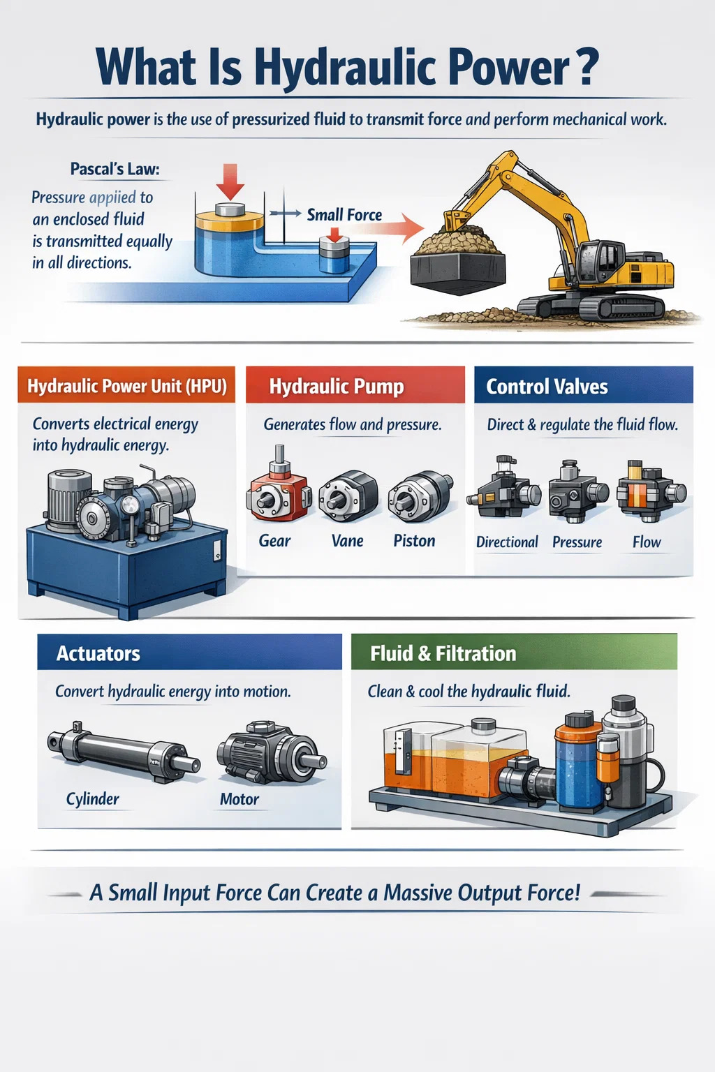
Hydraulic power is the use of pressurized fluid — almost always oil-based — to transmit force and perform mechanical work. The fundamental principle is Pascal's Law: pressure applied to an enclosed fluid is transmitted equally in all directions. This means a relatively small input force, acting on a small piston area, can be amplified into a massive output force on a larger piston area. In practical terms, that is why a compact hydraulic cylinder can lift a 30-ton excavator bucket, clamp a press with thousands of kilonewtons, or drive a ship's steering gear with precise, repeatable accuracy.
The energy source in a hydraulic system is the hydraulic power unit (HPU) — sometimes called a hydraulic power pack or power station. It converts electrical (or diesel) energy into hydraulic energy by driving a pump that pressurizes fluid, then distributes that pressure through hoses, valves, and cylinders to wherever work needs to be done. Without a properly sized HPU, even the most sophisticated downstream components cannot perform reliably.
Hydraulic power is measured in kilowatts (kW) or horsepower (HP), and system pressure is rated in bar or PSI. Industrial hydraulic systems commonly operate between 150 bar (2,175 PSI) and 350 bar (5,076 PSI), though ultra-high-pressure systems in aerospace or subsea applications can exceed 700 bar. Flow rate — measured in liters per minute (L/min) or gallons per minute (GPM) — determines actuator speed, while pressure determines force output.
A complete hydraulic circuit is composed of several interdependent components. Each one plays a specific role; a weakness in any part degrades overall system performance.
The HPU is the heart of the system. It typically consists of an electric motor or combustion engine, a hydraulic pump, a reservoir (tank) for fluid storage, a heat exchanger or cooling circuit, filtration assemblies, pressure relief valves, and an accumulator in many designs. The reservoir capacity ranges from a few liters in compact power packs to several thousand liters in large industrial stations. Motor ratings for industrial HPUs commonly span from 0.37 kW to over 500 kW, depending on application demand.
The pump converts mechanical energy into hydraulic flow. The three dominant pump types in industrial use are gear pumps (cost-effective, pressure up to ~250 bar), vane pumps (smooth flow, 70–175 bar), and piston pumps (highest pressure and efficiency, up to 420 bar or beyond). Variable displacement piston pumps are particularly valued because they adjust flow output to match load demand, cutting energy consumption by 20–40% compared with fixed-displacement alternatives.
Directional control valves route fluid to the correct actuator. Pressure control valves (relief, reducing, sequence) protect the circuit and manage force output. Flow control valves govern actuator speed. Modern systems increasingly use proportional or servo valves, which respond to electronic signals to enable closed-loop control — essential for CNC machines, injection molding, and robotics.
Actuators convert hydraulic energy back into mechanical work. Linear actuators (cylinders) produce push/pull force, while hydraulic motors produce rotary torque. Cylinder bore diameters range from 20 mm in compact machinery to over 1,000 mm in large press equipment. A cylinder with a 200 mm bore operating at 300 bar generates approximately 942 kN (about 96 metric tons) of clamping or lifting force.
Hydraulic fluid serves four functions simultaneously: transmitting power, lubricating internal components, dissipating heat, and sealing clearances. ISO VG 46 mineral oil is the most widely used grade for industrial machinery. Contamination is the primary cause of hydraulic failures — studies from the fluid power industry consistently show that over 70% of hydraulic system failures are contamination-related. Target cleanliness is typically ISO 4406 class 16/14/11 for servo systems and 18/16/13 for standard circuits.
Understanding the internal sequence of an HPU helps in both troubleshooting and system design.
An accumulator — a pressure vessel with a gas-charged bladder — can be added to store hydraulic energy and release it in burst-demand scenarios, allowing the HPU to use a smaller motor while still meeting peak load requirements. This technique is common in press-brake machines and die-casting equipment.
Engineers frequently compare hydraulic, electric, and pneumatic systems before committing to a design. Each approach has genuine strengths and concrete limitations.
| Criterion | Hydraulic | Electric (Servo) | Pneumatic |
|---|---|---|---|
| Force density | Very high (≥50 kN/kg) | Medium | Low (≤10 bar practical) |
| Precision / position control | High (servo-hydraulic) | Excellent | Limited |
| Energy efficiency | 60–85% (variable pump) | 85–95% | 25–35% |
| Overload protection | Inherent (relief valve) | Requires electronics | Inherent |
| Maintenance complexity | Medium–High | Low–Medium | Low |
| Typical operating pressure | 150–420 bar | N/A | 5–10 bar |
Hydraulic power holds a clear advantage in applications requiring very high force in a compact form. A hydraulic cylinder producing 500 kN might weigh 30 kg; achieving the same force with a ball-screw electric actuator could require a system weighing five times as much. Conversely, where sub-millimeter positioning accuracy and zero-leak requirements dominate, electric servo drives have largely replaced older hydraulic designs in machine tools and semiconductor equipment.
Modern electro-hydraulic systems combine both worlds: a variable-speed servo motor drives the hydraulic pump, delivering on-demand pressure and flow with efficiencies approaching electric actuation while retaining the force density of hydraulics. These servo-hydraulic power units are rapidly gaining adoption in injection molding and metal forming.
Hydraulic power is embedded in almost every sector that involves heavy load movement, forming, or force control. The global hydraulic equipment market was valued at approximately USD 40 billion in 2023 and is projected to grow at a CAGR of around 4.5% through 2030, driven by construction activity and industrial automation demand.
Excavators, bulldozers, cranes, and loaders depend entirely on hydraulic power for boom, arm, and bucket movement. A standard 20-ton excavator carries a hydraulic power unit delivering roughly 130–180 kW at system pressures around 350 bar. The load-sensing hydraulic systems on modern excavators automatically adjust pump displacement to match the instantaneous digging force required, reducing fuel consumption by up to 25% versus older constant-pressure systems.
Hydraulic presses for stamping, forging, deep drawing, and die casting require controlled, very high clamping forces that are difficult to achieve with mechanical drives. Large forging presses operate at 50 MN to 750 MN (meganewtons), powered by multiple HPUs working in parallel. Press brake machines for sheet metal bending use servo-hydraulic power units to achieve ±0.01 mm ram position repeatability — a specification that would be impossible with fixed-flow hydraulic circuits.
Subsea hydraulic systems control blowout preventers (BOPs), remotely operated vehicles (ROVs), and anchor windlasses on offshore platforms. High-pressure hydraulic power units rated at up to 690 bar are used in deepwater BOP control systems. Ship deck equipment — cranes, hatch covers, stern ramps — relies on centralized hydraulic power stations that distribute pressure throughout the vessel.
Injection molding machines, die casting machines, rubber vulcanization presses, and paper mill equipment all use dedicated HPUs. A typical 1,000-ton injection molding machine requires a hydraulic power unit rated at 55–75 kW with a flow rate of 100–200 L/min. Transitioning these machines to servo-hydraulic HPUs typically reduces electricity consumption by 30–60% per production cycle.
Aircraft flight control surfaces, landing gear, and thrust reversers depend on hydraulic systems operating at 207 bar (3,000 PSI) on older commercial aircraft and 345 bar (5,000 PSI) on newer designs such as the Boeing 787 and Airbus A380. The weight saving from operating at higher pressure allows smaller, lighter components. Military vehicles — tanks, howitzers, submarine periscopes — similarly rely on compact hydraulic power systems.
Wind turbine pitch control systems — which angle each blade to optimize power capture and prevent over-speed — use hydraulic accumulators and cylinders. Hydraulic pitch systems typically provide backup energy storage (in the accumulator) to feather blades safely during a grid failure, a safety function that electrohydraulic systems handle reliably even in extreme cold or heat.
Choosing a hydraulic power unit involves balancing multiple engineering and operational parameters. Undersizing the HPU leads to slow cycle times, overheating, and premature wear. Oversizing wastes capital and energy.
Start with the actuator load calculation. For a cylinder: Force (N) = Pressure (Pa) × Area (m²). If you need 200 kN from a 100 mm bore cylinder, you require at least 255 bar of working pressure (with a safety margin). Flow rate determines speed: a cylinder with a 100 mm bore extending at 50 mm/s needs approximately 24 L/min. The motor power required is P (kW) = [Pressure (bar) × Flow (L/min)] ÷ 600, adjusted for pump efficiency (typically 85–90%).
A common rule of thumb is to size the reservoir at 3–5 times the pump flow rate per minute. A pump delivering 40 L/min therefore needs a reservoir of 120–200 liters. This volume provides sufficient dwell time for entrained air to escape, heat to dissipate, and particles to settle before fluid recirculates to the pump intake.
Fixed-displacement gear pump HPUs are the most economical upfront but continuously deliver full flow regardless of demand, converting excess energy to heat. Variable-displacement piston pump HPUs cost roughly 2–3 times more initially but can reduce energy costs enough to achieve a payback period of 18–36 months in continuous production environments. For intermittent-duty cycles — where the machine is idle more than 50% of the time — a fixed-pump HPU with an unloading valve is often the better economic choice.
Servo-hydraulic (or electro-hydraulic) power units pair a variable-speed AC servo drive with a fixed-displacement pump. The drive adjusts motor RPM to match the exact flow and pressure required at each moment in the cycle. This architecture delivers energy savings of 40–70% versus conventional constant-speed HPUs in applications like injection molding, and it reduces noise levels by 10–15 dB(A) because the motor slows dramatically during holding phases.
Every watt of energy lost in a hydraulic system becomes heat in the oil. A system with a 37 kW motor operating at 75% efficiency generates roughly 9 kW of waste heat that must be removed continuously. Air-blast coolers are standard for mobile equipment; water-cooled heat exchangers are preferred for indoor industrial installations where ambient temperature is controlled. Failure to size cooling correctly shortens seal and pump life significantly — oil temperature exceeding 80°C accelerates oxidation, doubling fluid degradation rate for every 10°C rise.
The hydraulic fluid is as important as any mechanical component — it is simultaneously the energy carrier, lubricant, heat transfer medium, and sealant.
Fluid condition monitoring — tracking viscosity, acid number, particle count, and water content — extends system life and prevents unplanned downtime. Oil analysis programs at major industrial plants routinely achieve fluid service lives of 5,000–10,000 hours, versus the 2,000-hour default change interval recommended when no monitoring program is in place.
Even well-designed hydraulic systems develop problems over time. Knowing the symptoms and their root causes shortens troubleshooting time from hours to minutes.
| Symptom | Likely Cause | Diagnostic Step |
|---|---|---|
| Slow actuator speed | Low pump flow, clogged filter, worn pump | Measure flow at pump outlet; compare to rated value |
| High oil temperature | Cooler failure, excessive internal leakage, relief valve bypassing | Check cooler flow; monitor system pressure vs. relief setting |
| Noisy pump (cavitation) | Blocked suction strainer, low reservoir level, high fluid viscosity | Check vacuum at pump inlet; should be below 0.3 bar |
| Cylinder drift | Worn piston seals, contaminated directional valve spool | Isolate cylinder with manual valve; measure pressure decay |
| Pressure not reaching setpoint | Relief valve contaminated or set too low, pump worn | Dead-head pump against closed valve; read max pressure |
| Foamy oil | Air ingestion via suction line leak or low reservoir level | Inspect all suction connections; top up reservoir |
Condition-based maintenance programs that combine oil analysis, vibration monitoring on the pump and motor, and infrared thermal imaging of hose fittings and valve bodies can extend mean time between failures (MTBF) by 50–80% compared with time-based scheduled maintenance alone. Many modern hydraulic power units now include integrated IoT sensors and cloud connectivity, delivering continuous health data to maintenance teams without manual inspection.
Hydraulics has historically been criticized for poor energy efficiency compared with direct electric drives. This gap has narrowed significantly over the past decade through several technology developments.
The ISO 4413 standard and the newer ISO 16431 (hydraulic system efficiency benchmark) are now guiding new HPU specifications in Europe and increasingly in North America, pushing manufacturers to publish verified efficiency figures as part of procurement documentation.
Hydraulic systems store significant energy — a 200-liter reservoir at 300 bar contains roughly 3,000 kJ of stored energy, comparable to the kinetic energy of a small car traveling at 180 km/h. Failure to follow safety procedures causes serious injuries from high-pressure fluid injection and stored-energy releases.
Hydraulic pressure is one component of hydraulic power. Power equals pressure multiplied by flow rate: P (kW) = [bar × L/min] ÷ 600. A system at 300 bar with 5 L/min flow delivers 2.5 kW. Another at 100 bar with 50 L/min also delivers 8.3 kW. High pressure alone does not mean high power — flow rate matters equally.
With proper fluid maintenance and filter replacement, a well-built industrial HPU typically lasts 15–25 years. The pump is usually the first component to wear, with rated service lives of 8,000–20,000 hours depending on type, operating pressure, and fluid cleanliness. Gear pumps are the most durable in contaminated environments; piston pumps offer the longest life when fluid cleanliness is maintained at ISO 4406 class 16/14/11 or better.
Yes, provided it is designed for outdoor use. This means IP65 or higher electrical enclosure rating for the motor and control panel, stainless steel or coated reservoir and frame, low-temperature fluid (ISO VG 32 or synthetic fluids rated to -40°C for arctic conditions), and UV-resistant hose covers. Mobile HPUs on construction equipment are inherently designed for outdoor, all-weather operation.
The most common causes are an undersized or fouled heat exchanger, excessive internal leakage (which recirculates energy as heat without doing useful work), a relief valve set too close to the required working pressure (causing it to crack open frequently), and a reservoir too small to provide adequate thermal mass. Operating above 80°C oil temperature continuously will shorten component life significantly and should trigger investigation.
In an open-loop circuit, return fluid from the actuator goes back to the reservoir before being drawn into the pump again. This is the most common arrangement and simplifies cooling and filtration. In a closed-loop (or closed-center) circuit, return fluid goes directly back to the pump inlet, with only a small charge pump topping up leakage losses. Closed-loop circuits are used primarily with variable-displacement hydraulic motors for hydrostatic transmission in vehicles such as combines, compact track loaders, and industrial forklifts. They offer smooth, stepless speed control in both directions without a mechanical gearbox.
Sizing starts with the actuator requirements: maximum force (from load analysis), required speed (from cycle time requirements), and duty cycle (percentage of time under full load). From force and cylinder bore, calculate working pressure. From speed and bore, calculate required flow. Apply a service factor of 1.2–1.3 to account for inefficiencies. Select a pump and motor rated for those outputs, then size the reservoir and cooler for the resulting heat load. Many HPU manufacturers provide free sizing software — inputting these parameters generates a recommended configuration automatically.

This portable stacker hydraulic power unit is designed for portable stackers and integrates a high-pressure gear pump, a permanent magnet DC motor, a ...
See Details
This hydraulic power unit of full electric stacker is specially designed for full electric stacker. It is integrated by a high-pressure gear pump, a D...
See Details
This hydraulic power unit is specially designed for the clamping cylinder of the machine, too. It is integrated by a high-pressure gear pump.AC motor,...
See Details
This hydraulic power unit is specially designed for hot-melt butt welding machine and is integrated by high-pressure gear pump, AC motor central valve...
See Details
The hydraulic power unit is specially designed for the integrated hydraulic lifting column, which is integrated by a two-way gear pump, an AC oil imme...
See Details
ET series hydraulic lifting platform valve group is specially designed for various hydraulic lifting platforms. It can accurately control the lifting ...
See Details
The modular hydraulic valve block uses modular integrated design to accurately combine multiple hydraulic valves, greatly simplifying the system pipel...
See Details
The power unit manifold block for lifting platform is the core integrated component of the hydraulic system, and plays a key role in coordinating vari...
See Details
The regulating valve is a key device used in industrial control systems to adjust parameters such as fluid flow, pressure, and temperature. It can acc...
See Details
Proportional valve is a key component for realizing continuous and precise control of flow or pressure in hydraulic system. It can adjust output param...
See Details
No. 12 Tongji Road, Simen Town, Yuyao City

+86-0574-62130352
+86-18905846028

+86-0574-62130353

Copyright© Ningbo Panic Hydraulic Technology Co., Ltd. All Rights Reserved. China Hydraulic Power Units Manufacturers
