
 English
 中文简体
中文简体 русский
Mini Pallet Truck Hydraulic Power Unit
Cat:DC series hydraulic power unit
This hydraulic power unit is specially designed for all electric pallet truck.It consists of high voltage gear pump,permanent magnet DC motor and cent...
See DetailsContent
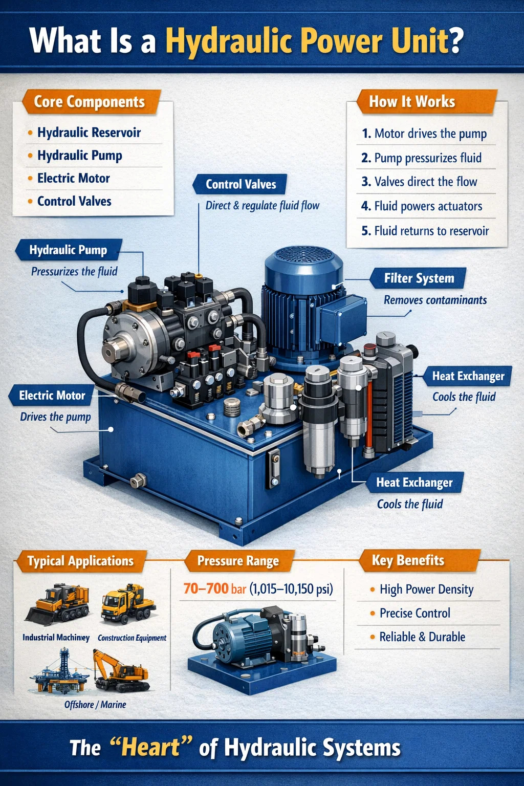
A hydraulic power unit (HPU) is a self-contained system that generates, controls, and transmits hydraulic energy to drive machinery and mechanical equipment. At its core, a hydraulic power unit converts mechanical energy — typically from an electric motor or internal combustion engine — into hydraulic energy in the form of pressurized fluid. This pressurized fluid is then directed through hoses and valves to actuators such as cylinders and hydraulic motors, which perform the actual mechanical work.
In plain terms: a hydraulic power unit is the "heart" of any hydraulic system. Without it, there is no fluid flow, no pressure, and no movement. Whether you are lifting a steel beam on a construction site, pressing metal parts in a manufacturing plant, or steering a large marine vessel, there is almost certainly a hydraulic power unit making it possible.
The term "power unit" is used because the assembly packages every essential element into one compact unit: the reservoir, the pump, the motor, the valves, the filters, and the instrumentation. This integrated design makes HPUs easy to install, maintain, and replace compared to systems where every component is mounted separately across a machine frame.
Hydraulic power units are used across nearly every heavy industry on the planet. A standard industrial HPU might operate at pressures between 70 bar (1,015 psi) and 350 bar (5,075 psi), with flow rates ranging from less than 1 liter per minute in small precision systems to over 1,000 liters per minute in large industrial presses or offshore equipment.
Understanding what makes up a hydraulic power unit helps clarify why it performs the way it does — and why certain failures occur. Every HPU, regardless of size or application, relies on the same fundamental set of components working together.
The reservoir stores the hydraulic fluid and serves several additional purposes: it allows heat to dissipate from the fluid, permits air bubbles to escape, and provides a settling area for contaminants. Reservoir capacity in industrial HPUs typically ranges from 10 liters in compact units to over 2,000 liters in large systems. The tank is usually made from steel or stainless steel, and it includes a breather/air filter, a sight glass for fluid level monitoring, a drain plug, and often a thermometer port.
The pump is the component that actually moves the fluid. It draws fluid from the reservoir and pushes it into the system under pressure. The most common pump types used in hydraulic power units are:
Pump selection directly affects efficiency. A well-matched piston pump can achieve volumetric efficiency above 95%, while a worn gear pump may drop below 85%, wasting energy as heat.
The prime mover drives the pump. In stationary industrial applications, this is almost always an electric motor. In mobile equipment or remote field locations without reliable electricity, a diesel or gasoline engine takes over. Motor power ratings in HPUs vary enormously — from 0.5 kW in small laboratory units to over 500 kW in large industrial presses or offshore rigs. The motor and pump are typically coupled directly through a bell housing and flexible coupling, or connected via a pump bracket.
Valves control the direction, pressure, and flow rate of the hydraulic fluid. Every hydraulic power unit includes at minimum a relief valve to protect the system from overpressure. Beyond that, directional control valves, pressure-reducing valves, flow control valves, and check valves are all commonly integrated into the HPU manifold block. Modern units often use electrohydraulic proportional or servo valves for precise, programmable control.
Contamination is the leading cause of hydraulic system failure. Studies across the industry consistently attribute 70% to 80% of hydraulic failures to fluid contamination. HPUs include suction strainers (typically 100–150 micron), pressure line filters (3–25 micron), and return line filters (3–10 micron) to keep the fluid clean. High-performance systems may also include offline kidney loop filtration that runs continuously regardless of system operation.
Hydraulic systems generate heat. If fluid temperature rises above approximately 60°C (140°F), fluid viscosity drops, efficiency falls, seals degrade, and oxidation accelerates. Most industrial HPUs include either an air-blast cooler or a water-cooled heat exchanger to maintain fluid temperature within the recommended operating range of 35–55°C.
Modern hydraulic power units are equipped with pressure gauges, thermometers, level switches, flow meters, and increasingly with digital sensors connected to a PLC or SCADA system. This instrumentation allows operators to monitor system health in real time and catch developing problems — such as a blocked filter or rising fluid temperature — before they cause a failure.
The operating cycle of a hydraulic power unit follows a straightforward sequence, repeated continuously during operation:
The beauty of this design is that hydraulic power units can transmit enormous amounts of force through relatively small components. Pascal's law states that pressure applied to a confined fluid transmits equally in all directions. A pump generating 200 bar of pressure acting on a cylinder with a 100 cm² bore area produces 200,000 N (approximately 20 tonnes) of force — from a pump that might fit in a briefcase.
Hydraulic power units come in a wide range of configurations designed for different environments, load requirements, and installation constraints.
The most common type. Built on a steel frame or directly on top of the reservoir tank, these units are designed for permanent installation in factories, workshops, and processing plants. They are connected to fixed machinery via rigid or flexible hose assemblies and typically operate on three-phase AC power.
Compact HPUs are designed to fit in tight spaces or to be integrated directly into machinery. They often have reservoir volumes under 20 liters and motor power ratings from 0.5 to 5 kW. These are widely used in automotive lifts, medical equipment, material handling tools, and small presses.
Designed for use on vehicles, trailers, or in outdoor locations without electrical supply. The prime mover is a gasoline or diesel engine, or in some cases a power take-off (PTO) shaft from a vehicle's transmission. Mobile HPUs power equipment such as cranes, excavator attachments, rescue tools, and road construction machinery.
Some applications require pressures well above the standard range. High-pressure HPUs using piston pumps and reinforced components operate at 500 to 700 bar (7,250 to 10,150 psi). These are used in hydraulic torque wrenches, structural testing equipment, metal forming, and subsea applications.
A growing category driven by energy efficiency requirements. Instead of running the motor at constant speed and throttling flow through valves (which wastes energy as heat), VSD HPUs use a frequency inverter to match motor speed — and therefore pump output — precisely to the load demand. Energy savings of 30% to 60% compared to fixed-speed systems are commonly documented in real-world installations, which is a significant operating cost reduction in heavy industry.
Used in oil and gas extraction, subsea pipeline control, and offshore platform operations. These units are engineered to withstand extreme external pressures, corrosive saltwater environments, and remote unmanned operation. They use specialized fluid, pressure-compensated reservoirs, and are often rated for depths exceeding 3,000 meters.
The range of industries relying on hydraulic power units is extensive. Below is an overview of major application sectors:
| Industry | Typical Application | Typical Pressure Range |
|---|---|---|
| Steel & Metal Processing | Rolling mills, forging presses, shears | 160–350 bar |
| Construction Equipment | Excavators, cranes, dump trucks | 200–350 bar |
| Oil & Gas | Wellhead control, BOP systems, pipeline valves | 207–690 bar |
| Marine & Shipbuilding | Steering gear, hatch covers, deck cranes | 100–250 bar |
| Automotive Manufacturing | Stamping presses, assembly fixtures, welding jigs | 150–300 bar |
| Aerospace & Defense | Landing gear, flight control surfaces, testing rigs | 207–350 bar |
| Agriculture | Tractor implements, harvester headers, bale presses | 140–250 bar |
| Waste Management | Refuse compactors, balers, skip lifters | 150–250 bar |
Beyond these sectors, hydraulic power units appear in theater stage machinery, hospital operating tables, wind turbine pitch control systems, injection molding machines, and even theme park rides. The combination of high force density, precise controllability, and mechanical simplicity makes hydraulic technology difficult to replace in applications where large forces must be delivered smoothly and reliably.
The hydraulic fluid is arguably the most important element in the entire system, yet it is frequently neglected. Fluid serves as both the power transmission medium and the lubricant for every moving part inside the pump, valves, and actuators. Choosing the wrong fluid or allowing it to degrade has serious consequences.
Fluid condition monitoring is now standard practice in serious maintenance programs. Regular oil analysis — checking viscosity, water content, particle count, and acid number — can predict pump wear and contamination events weeks before they cause failure. The cost of an oil analysis sample is typically under €30; the cost of a pump failure can be tens of thousands of euros in parts, labor, and lost production.
Selecting the right HPU requires understanding a set of fundamental technical parameters. Getting these wrong leads to either undersized equipment that fails under load or oversized equipment that wastes energy and investment.
The maximum working pressure determines component ratings throughout the entire circuit. Always specify both nominal operating pressure and peak pressure, since pressure spikes caused by valve switching or load shock can be 1.5 to 2 times the nominal value. The relief valve is set to limit maximum system pressure, typically 10–15% above the nominal working pressure.
Flow rate (liters per minute or gallons per minute) determines the speed of actuator movement. A cylinder extending at a specific speed requires a specific volume of fluid per unit of time. Flow rate is calculated from actuator geometry and required cycle time, then used to size the pump and motor. Undersizing flow leads to slow cycle times; oversizing means wasted energy through pressure relief.
Motor power (kW) is calculated from the product of flow rate and system pressure, divided by pump efficiency. The formula: P (kW) = (Q × p) / (600 × η), where Q is flow in L/min, p is pressure in bar, and η is overall pump efficiency (typically 0.85–0.92 for a modern piston pump). Undersized motors overheat and fail; significantly oversized motors run inefficiently at partial load.
A commonly applied rule of thumb sets reservoir volume at 3 to 5 times the pump flow rate per minute. A pump delivering 50 L/min should therefore have a reservoir of 150–250 liters. This ensures adequate dwell time for fluid cooling and air release. High-duty-cycle or high-heat-load applications require larger reservoirs or supplementary cooling.
Filter fineness is expressed as a Beta ratio (βx) at a given particle size in microns. A filter rated β10 = 200 means it removes 99.5% of particles 10 microns and larger per pass. High-performance servo valve systems require ISO cleanliness levels of ISO 16/14/11 or better, while general industrial circuits might tolerate ISO 18/16/13. Specifying filtration correctly from the start prevents premature servo valve failures, which are expensive to replace.
Engineers designing machinery must choose between hydraulic, electric, and pneumatic power transmission. Each has genuine strengths and weaknesses, and the right answer depends heavily on the application.
| Parameter | Hydraulic Power Unit | Electric Actuator | Pneumatic System |
|---|---|---|---|
| Force density | Very high | Medium | Low–medium |
| Position control accuracy | High (with servo) | Very high | Low–medium |
| Energy efficiency | Medium (VSD improves) | High | Low |
| Maintenance complexity | Medium | Low | Low |
| Overload protection | Excellent (relief valve) | Good (electronic) | Good |
| Operating environment | Harsh / outdoor / hazardous | Clean / indoor preferred | Moderate |
| Typical cost (installed) | Medium–high | Medium–high | Low–medium |
Hydraulic power units remain the dominant choice wherever forces exceed roughly 10 kN, where stall force must be maintained indefinitely without overheating the drive, or where the environment is too harsh for sensitive electric components. For lighter-duty, clean-room, or highly precise positioning applications, electromechanical systems are increasingly competitive and in some cases superior.
Even well-designed HPUs will develop problems over time without proper maintenance. Recognizing the symptoms early prevents minor issues from becoming major failures.
Causes include a blocked or fouled heat exchanger, low fluid level reducing heat capacity, excessive bypass through a relief valve (indicating the system is doing more work than the circuit allows), or a failed cooling fan or water supply. Prevention requires regular cleaning of cooler cores, maintaining correct fluid levels, and checking that system pressure matches actual load requirements.
Cavitation occurs when the pump inlet pressure drops below fluid vapor pressure, causing vapor bubbles to form and then implode violently inside the pump housing. It produces a characteristic grinding or rattling noise and causes rapid erosion of pump internals. Common causes are a blocked suction strainer, fluid that is too cold and therefore too viscous, a suction line that is too small or too long, or a reservoir that is running low. Damage from severe cavitation can destroy a pump within hours.
Air entering the hydraulic circuit produces spongy actuator response, noisy operation, and accelerated fluid oxidation. Sources include low fluid level (pump drawing in air from the reservoir surface), leaking suction line fittings, or a damaged shaft seal on the pump. Aeration is often confused with cavitation since both produce noise, but aeration fluid typically looks milky or frothy in the reservoir sight glass.
The primary source of hydraulic failures, as mentioned earlier. Contamination enters during maintenance, through worn seals, through breather filters that are not serviced, and by ingression through cylinder rod seals. The solution is a rigorous contamination control program: use clean fluid from sealed containers, filter new fluid before adding it, maintain filter elements on schedule (typically every 2,000 to 4,000 operating hours for standard industrial systems), and sample oil regularly.
External fluid leakage is both a maintenance problem and a safety hazard — hydraulic fluid on a floor creates slip risks, and high-pressure injection injuries from pinhole leaks are a serious industrial safety concern. Regular inspection of hose connections, valve body gaskets, and cylinder rod seals, combined with prompt replacement of worn seals, is the appropriate response. Never check for leaks by running a hand over high-pressure lines.
A structured maintenance approach significantly extends HPU service life and reduces unplanned downtime. The following schedule represents standard industrial practice:
Hose assemblies deserve special mention. Most manufacturers recommend replacing hydraulic hoses every 6 years regardless of condition, as internal degradation is not visible externally. A burst hose at 300 bar can cause severe injuries and fires.
Hydraulic systems have historically been criticized for energy inefficiency. A conventional fixed-displacement pump running at constant speed and throttling excess flow through a pressure relief valve or proportional valve converts a significant portion of input energy directly into heat. In a traditional industrial press with a 37 kW motor, it is not uncommon for 30–40% of input energy to be wasted as heat in the hydraulic circuit.
The industry has responded with several design advances:
As noted earlier, matching motor speed to demand through a frequency inverter eliminates throttling losses. The HPU only draws as much power as the load actually requires at any given moment. In injection molding machines, where the hydraulic load varies enormously across the machine cycle, VSD HPUs have demonstrated energy savings of 40–60% in documented case studies.
A load-sensing hydraulic power unit uses a variable displacement pump that continuously monitors downstream pressure demand and adjusts its output displacement to match. The pump delivers only the pressure and flow required by the load — no more. This approach is common in mobile equipment (excavators, cranes) where fuel efficiency is critical, and is increasingly used in industrial applications.
A newer development integrates a small electric motor, bidirectional pump, and hydraulic cylinder into a single compact assembly. Each actuator has its own self-contained HPU. This eliminates long hydraulic lines, reduces fluid volume, and improves overall system efficiency. EHAs are gaining ground in aerospace, automotive assembly, and precision industrial automation.
Modern hydraulic power units are increasingly fitted with digital pressure transmitters, flow sensors, particle counters, and vibration monitors connected to industrial IoT platforms. This enables predictive maintenance — detecting bearing wear, pump efficiency loss, or filter bypass conditions through trend analysis of sensor data, rather than waiting for a failure or relying on time-based maintenance intervals. Companies implementing condition monitoring programs report reductions in unplanned hydraulic downtime of 50% or more compared to time-based maintenance alone.
Selecting an HPU involves more than picking a pressure and flow rating off a catalog page. A well-specified hydraulic power unit must match the application's operational demands, environmental conditions, and maintenance capabilities.
Working with an experienced hydraulic system engineer during the specification phase consistently produces better outcomes than selecting from standard catalog units and adapting them to the application after the fact. The upfront engineering investment is small relative to the cost of an incorrectly specified HPU running in a production environment.

This hydraulic power unit is specially designed for all electric pallet truck.It consists of high voltage gear pump,permanent magnet DC motor and cent...
See Details
This portable stacker hydraulic power unit is designed for portable stackers and integrates a high-pressure gear pump, a permanent magnet DC motor, a ...
See Details
This hydraulic pump station is specially designed for a self-propelled aerial work vehicle. It is composed of 2 series side inlet and side outlet gear...
See Details
This hydraulic power unit is specially designed for a mobile hydraulic lifting table, which is integrated with a high-pressure gear pump. permanent ma...
See Details
This DC double acting power unit is an integrated hydraulic system designed for various equipment that requires efficient hydraulic drive. It is suita...
See Details
This hydraulic power unit is controlled by a brushless motor and can be divided into external and internal drives based on power. It is integrating co...
See Details
The hydraulic power unit is specially designed for the integrated hydraulic lifting column, which is integrated by a two-way gear pump, an AC Oil imme...
See Details
This hydraulic power unit is designed to meet extreme security needs, especially for critical occasions where large vehicles such as heavy trucks and ...
See Details
The power unit manifold block for lifting platform is the core integrated component of the hydraulic system, and plays a key role in coordinating vari...
See Details
The hydraulic valve block centrally installs various hydraulic valves through the internal precision flow channel, solves the problems of bloated and ...
See Details
No. 12 Tongji Road, Simen Town, Yuyao City

+86-0574-62130352
+86-18905846028

+86-0574-62130353

Copyright© Ningbo Panic Hydraulic Technology Co., Ltd. All Rights Reserved. China Hydraulic Power Units Manufacturers
