
 English
 中文简体
中文简体 русский
Dump trailer power unit
Cat:DC series hydraulic power unit
This hydraulic power unit is specially designed for dump trailers. It is integrated by a high-pressure gear pump, DC carbon brush machine, central val...
See DetailsContent
Hydraulics is the branch of physics and engineering that studies the mechanical behavior of liquids under pressure. At its core, the science rests on three foundational principles: Pascal's Law, the continuity equation, and Bernoulli's principle. These three laws govern everything from a simple hydraulic jack to a complex industrial Hydraulic Power Unit driving heavy manufacturing machinery. Understanding them is not an academic exercise — it directly determines how systems are designed, sized, and maintained in real-world applications.
Hydraulic systems can transmit enormous forces over long distances with very little energy loss. A pressure of just 3,000 psi (207 bar) applied across a piston with a 10-square-inch face delivers a pushing force of 30,000 lbf — enough to bend structural steel or lift a loaded truck axle. That kind of leverage is only possible because liquids, unlike gases, are nearly incompressible, and the underlying physics allows force to be multiplied, redirected, and precisely controlled in ways that mechanical linkages cannot match.
Blaise Pascal formulated his principle in the 17th century: pressure applied to an enclosed, static fluid is transmitted equally in all directions throughout the fluid and to the walls of the container. Mathematically, this is expressed as:
Where P is pressure (Pa or psi), F is applied force (N or lbf), and A is the cross-sectional area (m² or in²). The practical implication is profound: if you push on a small piston and connect it through fluid to a larger piston, the force is amplified in proportion to the ratio of the areas.
Imagine a small cylinder with a 1 in² piston generating 500 lbf. That delivers 500 psi of system pressure. Connect that same 500 psi to a cylinder with a 20 in² piston, and the output force becomes 10,000 lbf — a 20:1 mechanical advantage with no gears or levers involved. This is exactly why hydraulic cylinders are used to clamp injection molds, press metal stampings, and extend excavator arms.
In a Hydraulic Power Unit, Pascal's Law underpins the design of every actuator in the circuit. The pump generates pressure; Pascal's Law ensures that pressure reaches every actuator simultaneously and uniformly — assuming the system is static and the fluid column is the same height at each branch (gravity effects aside). Relief valves, pressure-reducing valves, and sequence valves all exploit this principle to route force to the right actuator at the right time.
Pascal's Law also accounts for the pressure added by a column of fluid due to gravity:
Where ρ is fluid density (kg/m³), g is gravitational acceleration (9.81 m/s²), and h is height (m). For hydraulic oil at roughly 870 kg/m³, every meter of vertical column adds about 0.085 bar (1.24 psi) of pressure. In most industrial systems this is negligible, but in subsea and mining applications where vertical runs can exceed 100 m, this head pressure becomes a critical design parameter.
While Pascal's Law governs static pressure, the continuity equation governs the behavior of fluid in motion. It states that, for an incompressible fluid flowing through a pipe, the volumetric flow rate must remain constant — meaning the product of cross-sectional area and fluid velocity is constant at any point along the flow path:
Where Q is flow rate (L/min or gpm), A is pipe cross-section (m²), and v is fluid velocity (m/s). If you reduce the pipe diameter, the fluid must accelerate to maintain the same flow rate. If you increase it, velocity drops.
Most hydraulic engineers target fluid velocities in the range of 2–4 m/s for pressure lines and 1–2 m/s for return lines. Higher velocities increase turbulence (measured by Reynolds number), which causes pressure drop, heat generation, and erosion of valve seats and port edges. Lower velocities in return lines prevent cavitation at the pump inlet — arguably the single most destructive condition in any hydraulic circuit.
When specifying a Hydraulic Power Unit for a given application, the continuity equation drives the selection of tubing diameter, manifold port sizes, and filter element ratings. A 45 L/min pump feeding through a 10 mm bore line produces approximately 9.5 m/s — far above the acceptable limit. Increasing the bore to 16 mm drops velocity to roughly 3.7 m/s, which falls within the recommended range for pressure lines.
The same equation determines actuator speed. A hydraulic cylinder with a 63 mm bore (area ≈ 31.2 cm²) extending at 50 mm/s consumes a flow of:
Knowing this, the system designer can properly size the pump, the directional control valve, and the flow control valve — all before any hardware is purchased. The continuity equation is the arithmetic backbone of every hydraulic circuit design.
Bernoulli's equation is the energy conservation law for fluid flow. It states that for an incompressible, frictionless fluid flowing along a streamline, the total mechanical energy per unit volume remains constant:
This equation tells us that as fluid velocity increases, static pressure must decrease — and vice versa. The three terms represent static pressure energy, kinetic energy, and potential (gravitational) energy respectively.
Bernoulli's principle directly explains the behavior of several critical hydraulic components:
For a well-designed Hydraulic Power Unit, Bernoulli's principle is the reason engineers insist on a short, large-bore suction line, minimal bends, and a properly sized strainer — not a fine filter — at the pump inlet. Every restriction on the suction side increases fluid velocity locally, depresses static pressure, and moves the system closer to the cavitation threshold.
The three classic principles above assume an ideal, frictionless, incompressible fluid. Real hydraulic oil is none of these things. Viscosity — the fluid's internal resistance to shear — is the dominant real-world property that modifies how Pascal's Law, continuity, and Bernoulli apply in actual systems.
Two measures of viscosity matter in hydraulics. Dynamic viscosity (μ, in Pa·s or cP) measures resistance to shear stress directly. Kinematic viscosity (ν, in mm²/s or cSt) is dynamic viscosity divided by density and is the value almost universally quoted on hydraulic fluid datasheets. Most industrial hydraulic systems operate with oils in the ISO VG 32 to ISO VG 68 range, meaning kinematic viscosities of 32–68 cSt at 40°C.
The Reynolds number (Re) predicts whether flow in a pipe is laminar or turbulent:
Below Re ≈ 2,300, flow is laminar — smooth, predictable, low friction loss. Above Re ≈ 4,000, flow is turbulent — chaotic, higher friction losses, greater heat generation, and increased potential for erosion and noise. Most hydraulic pressure lines operate in the laminar regime, which is why Hagen-Poiseuille's law applies to pressure drop calculations in those lines:
This equation shows that pressure drop scales with the fourth power of diameter — halving the pipe diameter increases pressure drop by a factor of 16. This is why undersized return lines and case-drain lines are among the most common causes of component failure in field-installed hydraulic circuits.
Hydraulic oil viscosity changes dramatically with temperature. A typical ISO VG 46 mineral oil drops from about 220 cSt at 0°C to 46 cSt at 40°C to roughly 15 cSt at 80°C. At low viscosity, internal leakage across pump pistons, valve spools, and motor commutators increases significantly — reducing volumetric efficiency and causing erratic speed control. At high viscosity (cold start), cavitation risk rises because the thick fluid resists flowing into the pump intake fast enough. Maintaining oil temperature in the 40–60°C operating window is a core design requirement for any Hydraulic Power Unit equipped with a heat exchanger and thermostat.
A Hydraulic Power Unit (HPU) is the self-contained assembly — typically comprising a motor, pump, reservoir, filtration, heat exchanger, and control valves — that generates and conditions pressurized fluid for a hydraulic circuit. Every major component embodies one or more of the principles discussed above.
| HPU Component | Primary Scientific Principle | Design Implication |
|---|---|---|
| Hydraulic pump | Pascal's Law + Continuity | Displacement (cc/rev) × speed (rpm) = flow; torque determines pressure |
| Relief valve | Pascal's Law | Limits maximum system pressure; poppet lifts when F = P × A (spring set) |
| Suction strainer | Bernoulli's principle | Fine mesh creates velocity increase, pressure drop, and cavitation risk |
| Flow control valve | Continuity + Bernoulli | Orifice area controls velocity; ΔP across orifice governs Q |
| Hydraulic cylinder | Pascal's Law + Continuity | Force = P × bore area; speed = Q / bore area |
| Heat exchanger | Viscosity / thermodynamics | Maintains oil in 40–60°C window to preserve viscosity and seal integrity |
| Reservoir | Continuity + fluid dynamics | Volume = 3–5× pump flow (L/min) allows air release, heat dissipation, and sedimentation |
A real hydraulic pump never delivers 100% of its theoretical displacement per revolution because viscosity allows a small amount of fluid to leak across internal clearances from high-pressure to low-pressure zones. Volumetric efficiency typically runs 90–98% for a well-maintained axial piston pump in the mid-speed range. As pressure rises, leakage increases and volumetric efficiency drops. As oil viscosity drops (hot or wrong grade), leakage increases further. Understanding these relationships allows engineers to predict actual output flow at any given operating point and specify a motor with adequate power reserves — typically 10–15% above the calculated demand.
Hydraulic power is the product of pressure and flow rate. In SI units:
In imperial units: P (hp) = Q (gpm) × ΔP (psi) / 1714. This relationship is the first calculation performed in any Hydraulic Power Unit sizing exercise. A system requiring 80 L/min at 200 bar needs a minimum theoretical input power of:
With an overall system efficiency of around 85% (pump mechanical + volumetric × motor), the electric motor must be rated for at least 31.4 kW. Undersizing the motor leads to thermal overloading; oversizing wastes capital and increases no-load power consumption.
The laws of thermodynamics mean that all energy losses in a hydraulic circuit ultimately convert to heat. Understanding the sources of loss allows designers to minimize them:
A well-engineered Hydraulic Power Unit addresses all four loss mechanisms at the design stage: through variable displacement pumps, properly sized conductors, tight-tolerance components with controlled clearances, and pre-fill accumulators on fast-acting circuits.

Hydraulic engineers routinely treat oil as incompressible, and for slow or steady-state applications this is a valid simplification. But oil is not perfectly incompressible. The bulk modulus of a typical mineral hydraulic oil is approximately 14,000–17,000 bar (1.4–1.7 GPa). This means that at 200 bar, oil compresses by roughly 1.2–1.4% of its volume.
In most systems this is inconsequential. But in three scenarios it becomes critically important:
Cavitation and aeration are the two most destructive phenomena in hydraulics, and both are direct consequences of the fluid physics discussed above.
Cavitation occurs when local static pressure drops below the fluid's vapor pressure, typically around 0.02–0.05 bar absolute for mineral oils at operating temperature. Bernoulli's principle explains why: restricted flow passages raise velocity, which lowers static pressure. When the pressure falls below vapor pressure, dissolved gas and oil vapor flash into bubbles. When these bubbles enter a high-pressure zone, they collapse asymmetrically, producing localized pressure spikes in excess of 1,000 bar and temperatures above 1,000°C at the collapse point. The result is pitting erosion — visually similar to sand blasting — on pump barrels, valve seats, and motor porting plates.
Signs of cavitation include a loud, crackling noise from the pump (distinct from the whine of aeration), rapid loss of volumetric efficiency, and accelerated metallic contamination in oil samples. Prevention is straightforward: maintain adequate positive pressure at the pump inlet (NPSH — Net Positive Suction Head), use large-bore suction lines, mount the pump close to and below the reservoir, and avoid fine strainers on the suction side.
Aeration is the entrainment of free air or gas into the fluid, distinct from dissolved gas. Sources include low oil level (suction picks up air), leaking shaft seals on the pump (air ingestion under suction vacuum), and poorly designed return lines that dump oil above the fluid surface, whipping air into the reservoir. Aerated oil is compressible, spongy, prone to oxidation (air accelerates thermal degradation), and damaging to pump surfaces through micro-diesel effects — entrained air bubbles auto-ignite under rapid compression, locally charring the oil and depositing varnish on metal surfaces.
A hydraulic pump converts mechanical energy into fluid power by creating a flow of pressurized oil. Three fundamental pump types dominate industrial and mobile applications, each applying the core scientific principles differently.
External gear pumps use two meshing gears rotating inside a close-tolerance housing. As teeth disengage on the inlet side, they create an expanding volume (low pressure) that draws in fluid. As they re-mesh on the outlet side, the enclosed fluid is positively displaced into the pressure line. Gear pumps are fixed displacement, robust, and simple. Operating pressures typically reach 200–250 bar, making them standard choices in construction equipment, agricultural machinery, and the low-pressure circuits of industrial Hydraulic Power Units.
Vane pumps use spring-loaded or pressure-loaded blades that slide radially in slots within an eccentric rotor. As the rotor turns, the vane tip follows the cam ring profile, creating expanding and contracting chambers. They deliver smoother flow with lower noise than gear pumps and operate up to 175 bar, making them popular in machine tool, injection molding, and power steering applications where noise is a concern.
Axial piston pumps use multiple pistons (typically 7 or 9) arranged in a circular pattern within a rotating cylinder block. The pistons reciprocate in and out as the block rotates against an angled swashplate. Displacement is controlled by changing the swashplate angle, making these pumps variable displacement — capable of delivering exactly the flow the system demands at any given moment. Operating pressures routinely reach 350–420 bar, and some designs are rated to 700 bar. They are the pump of choice for high-performance industrial Hydraulic Power Units, servo-controlled presses, and all major mobile hydraulic systems including excavator main circuits.
| Pump Type | Max Pressure (bar) | Variable Displacement | Typical Application | Noise Level |
|---|---|---|---|---|
| External Gear | 200–250 | No | Construction, agriculture | High |
| Vane | 150–175 | Some models | Machine tools, molding | Low–Medium |
| Axial Piston | 350–420+ | Yes | Industrial HPU, mobile | Medium |
| Radial Piston | Up to 700 | Yes | High-force presses, test rigs | Low–Medium |
Understanding the principles is one thing; applying them systematically during design is another. The following sequence reflects how experienced hydraulic system engineers approach a new application:
Each step directly applies one or more of the core principles discussed in this article. None of them requires guesswork — hydraulics is a deterministic science, and a Hydraulic Power Unit sized through this process will perform exactly as specified from day one, provided the fluid is maintained correctly.
Particle contamination is responsible for 70–80% of hydraulic component failures according to data from major pump and valve manufacturers. The reason is rooted directly in the physics of the components: clearances between pump pistons and cylinder bores, or between spool valves and their bores, are typically 5–25 micrometers. Particles larger than these clearances cause three-body abrasive wear, which generates more particles in a self-accelerating degradation cycle.
Fluid contamination also degrades performance in ways that are less obvious but equally destructive:
Good hydraulic maintenance is not a matter of opinion or habit — it follows logically from the physics. Each maintenance task maps to a specific failure mechanism rooted in the principles above:
A Hydraulic Power Unit that is maintained with a thorough understanding of the underlying science will reliably operate for 20,000–50,000 hours before major overhaul — a service life that begins to look much shorter if contamination control and thermal management are neglected.

This hydraulic power unit is specially designed for dump trailers. It is integrated by a high-pressure gear pump, DC carbon brush machine, central val...
See Details
Designed for hydraulic lifting platforms, this lifting platform power unit integrates a high-pressure gear pump, AC motor, center valve block, cartrid...
See Details
This hydraulic power unit is specially designed for hot-melt butt welding machine and is integrated by high-pressure gear pump, AC motor central valve...
See Details
This hydraulic power unit is designed to meet extreme security needs, especially for critical occasions where large vehicles such as heavy trucks and ...
See Details
The V3068 hydraulic valve group is an electric check valve group designed for hydraulic systems. It is mainly used to prevent the backflow of media, e...
See Details
The power unit manifold block for lifting platform is the core integrated component of the hydraulic system, and plays a key role in coordinating vari...
See Details
The hydraulic valve block centrally installs various hydraulic valves through the internal precision flow channel, solves the problems of bloated and ...
See Details
The multi-connection hydraulic integrated valve block is an efficient integrated component of the hydraulic system, including two-connection, three-co...
See Details
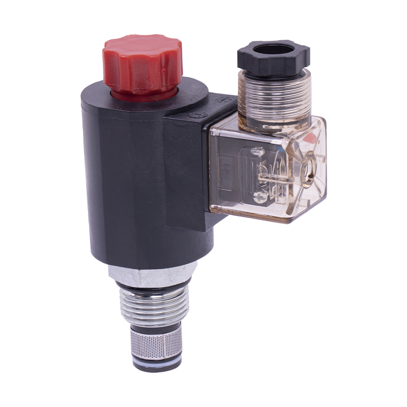
The regulating valve is a key device used in industrial control systems to adjust parameters such as fluid flow, pressure, and temperature. It can acc...
See Details
The cartridge hydraulic control check valve controls the on/off and flow direction of the hydraulic oil to start, stop, change direction and lock the ...
See Details
No. 12 Tongji Road, Simen Town, Yuyao City

+86-0574-62130352
+86-18905846028

+86-0574-62130353

Copyright© Ningbo Panic Hydraulic Technology Co., Ltd. All Rights Reserved. China Hydraulic Power Units Manufacturers
