
 English
 中文简体
中文简体 русский
Hydraulic tailboard power unit
Cat:DC series hydraulic power unit
This hydraulic power unit is specially designed for the hydraulic tail plate. The vehicle tail plate hydraulic power unit is a power unit used for the...
See DetailsContent
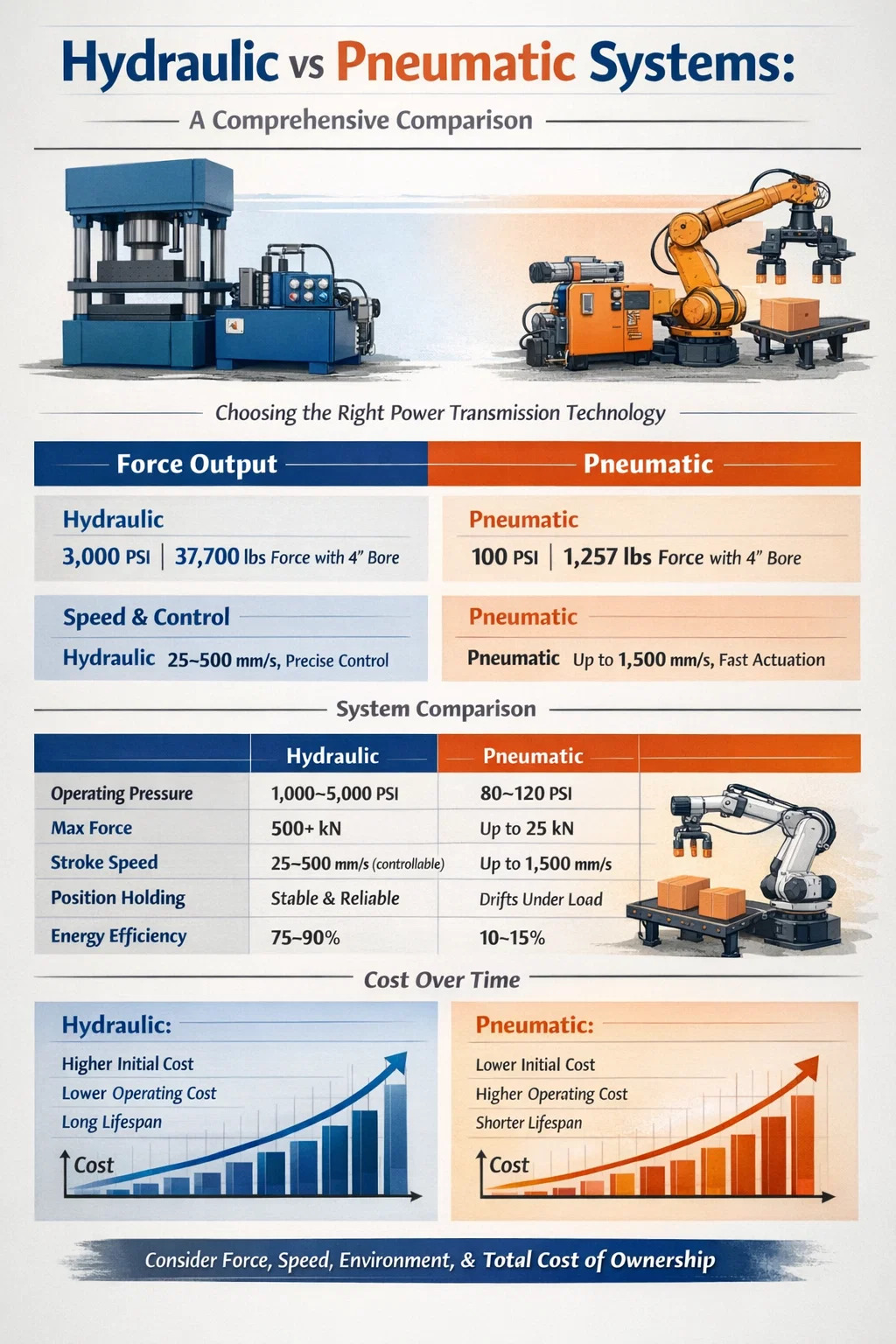
If you need to move heavy loads with precision, hydraulic systems win outright. If you need clean, fast, lightweight actuation for moderate forces, pneumatic systems are the smarter choice. The decision between hydraulic vs pneumatic comes down to four factors: force requirements, speed, environment, and total cost of ownership. Most industrial buyers get this wrong by focusing only on upfront equipment price—and end up paying for it over years of operation.
Hydraulic systems, anchored by a hydraulic power unit, operate on pressurized fluid—typically mineral oil—at pressures ranging from 1,000 to 5,000 PSI, with some specialized systems reaching 10,000 PSI or more. Pneumatic systems use compressed air, generally at 80 to 120 PSI. That pressure gap alone explains why hydraulics can lift a 50-ton press and pneumatics are better suited to operating a clamping fixture or a paint sprayer.
This article breaks down every major comparison point—force density, energy efficiency, maintenance demands, cost structures, safety profiles, and the specific industrial applications where each system performs best. By the end, you will have a clear framework for selecting the right power transmission technology for your operation.
Force output is the single most important differentiator when comparing hydraulic vs pneumatic systems. Pascal's Law governs both: pressure multiplied by area equals force. But because hydraulic fluid is incompressible and can be pressurized to extreme levels, a hydraulic cylinder generates dramatically more force per unit of size than a pneumatic cylinder of the same bore diameter.
Consider a cylinder with a 4-inch bore. At 100 PSI (typical pneumatic line pressure), it produces approximately 1,257 pounds of force. At 3,000 PSI (typical hydraulic system pressure), the same bore diameter generates 37,700 pounds of force—roughly 30 times more. This is why hydraulic power units are the backbone of metal stamping presses, injection molding machines, mining equipment, and heavy construction machinery.
Pneumatic systems typically max out at 25 kN (about 5,600 lbf) for standard industrial cylinders, while hydraulic actuators routinely exceed 500 kN in standard configurations. For any application requiring sustained high force—forging, compaction, material testing, heavy clamping—a hydraulic power unit is not optional; it is the only viable solution.
Hydraulic systems can hold a load in place mid-stroke indefinitely without continuous energy input, simply by closing a valve. Pneumatic systems cannot do this reliably—compressed air is compressible, so a locked pneumatic cylinder will drift under load. For applications like holding a press die or maintaining clamp force during a welding operation, hydraulics provide a stable, locked position that pneumatics fundamentally cannot match.
Pneumatic systems actuate faster. Air is compressible and light, which means pneumatic cylinders extend and retract with snappy, high-velocity strokes. Cycle times of under 0.5 seconds for a full stroke are common in pneumatic pick-and-place systems. High-speed pneumatic hammers, stapling machines, and packaging line conveyors rely on this rapid actuation capability.
Hydraulic systems are slower at the stroke level, though controllable. Because hydraulic fluid is dense and incompressible, moving it through a circuit takes more energy and the actuator velocity is directly tied to flow rate from the hydraulic power unit's pump. A standard hydraulic cylinder might complete a 12-inch stroke in 1 to 3 seconds—adequate for most heavy-duty applications, but not suitable for tasks requiring hundreds of cycles per minute.
However, speed control in hydraulic systems is far more precise. By adjusting flow control valves or using variable-displacement pumps in the hydraulic power unit, operators can dial in exact velocities throughout a stroke—critical for operations like slow-approach die stamping or controlled extrusion. Pneumatic speed control is rougher and more sensitive to line pressure fluctuations.
| Parameter | Hydraulic | Pneumatic |
|---|---|---|
| Typical operating pressure | 1,000–5,000 PSI | 80–120 PSI |
| Max force (standard cylinder) | 500+ kN | Up to 25 kN |
| Typical stroke speed | 25–500 mm/s (controllable) | Up to 1,500 mm/s |
| Speed controllability | Excellent (fine control) | Moderate (harder to fine-tune) |
| Position holding under load | Reliable (incompressible fluid) | Poor (compressible air drifts) |
Energy efficiency is frequently misunderstood in the hydraulic vs pneumatic debate. Pneumatic systems are often assumed to be more efficient because they use plant air. In practice, they are often the least efficient power transmission method in a factory. Generating compressed air is notoriously wasteful—only about 10 to 15% of the electrical energy fed into an air compressor actually reaches the point of use as useful mechanical work. Leaks, heat generation, and pressure drops consume the rest.
Hydraulic systems, especially those using modern hydraulic power units with variable-displacement piston pumps and load-sensing controls, achieve overall efficiencies of 75 to 90% in well-maintained, properly sized systems. A variable-displacement pump only outputs what the circuit demands; a fixed-displacement pump in a system with low demand will dump excess flow over the relief valve as heat—a significant energy waste that system designers must account for.
For low-duty-cycle operations—where a cylinder actuates once every several seconds—the continuous idle energy consumption of a running hydraulic power unit can outweigh its efficiency advantage. In these scenarios, pneumatic systems powered by centralized plant air may make more economic sense, since the air compressor is shared across dozens of machines.
Every hydraulic power unit generates heat through fluid friction, valve pressure drops, and pump inefficiency. A typical industrial hydraulic power unit operating at 20 kW input might dissipate 3 to 6 kW as heat into the reservoir. Without adequate heat exchange—either through reservoir surface area, air blast coolers, or water-cooled heat exchangers—oil temperature climbs past the safe operating range of 60°C (140°F), accelerating seal degradation and oil oxidation. Pneumatic exhaust air carries heat away automatically; hydraulic systems require deliberate thermal management as part of system design.
A hydraulic power unit (HPU) is the heart of any hydraulic system. It is a self-contained package that generates, stores, filters, and conditions pressurized hydraulic fluid. Understanding its components helps clarify why hydraulic systems behave differently from pneumatic setups—and why they cost more upfront.
Pneumatic systems have no equivalent to the hydraulic power unit as a packaged system. Instead, they rely on a centralized air compressor, dryer, receiver tank, and distribution piping—all typically shared infrastructure. This simplifies individual machine design but creates a dependency on plant-wide air quality and pressure consistency.
Maintenance is where the hydraulic vs pneumatic comparison becomes most consequential for operations managers. Both systems require regular attention, but the nature and consequence of neglect differ sharply.
Hydraulic systems are sensitive to fluid contamination. Over 80% of hydraulic system failures are attributed to contaminated oil. Particulate contamination scores servo valve spools, scratches cylinder bores, and accelerates pump wear. A rigorous maintenance program for a hydraulic power unit includes:
External oil leaks are the most visible hydraulic failure mode. Even a small seal leak can create floor hazards, environmental compliance issues, and fire risks if oil contacts hot surfaces. ISO 23309 and local environmental regulations may require spill containment systems around hydraulic equipment in certain industries.
Pneumatic maintenance is simpler at the machine level but often neglected at the infrastructure level. Key tasks include:
The biggest pneumatic maintenance failure mode is invisible: air leaks that drain compressor capacity silently. A 3mm hole in a distribution line at 100 PSI can waste over 1 kW of compressor energy continuously. Ultrasonic leak detection tools are essential for facilities managing large pneumatic networks.
Purchase price is where pneumatic systems appear most attractive. A pneumatic cylinder and valve assembly for a light-duty application might cost $50 to $500. A comparable hydraulic cylinder with valve and manifold can run $500 to $5,000—and a dedicated hydraulic power unit for a single machine adds another $2,000 to $30,000 depending on size and specification.
However, lifetime cost analysis tells a more balanced story. Pneumatic systems are inexpensive to buy and install, but expensive to run. In facilities where compressed air is generated at a fully loaded cost (electricity, maintenance, capital depreciation) of $0.25 to $0.35 per 1,000 standard cubic feet, high-duty-cycle pneumatic consumers become significant energy line items. A single 2-inch bore pneumatic cylinder cycling 60 times per minute for two 8-hour shifts can consume the equivalent of 2 to 4 kW of electrical energy continuously.
| Cost Category | Hydraulic | Pneumatic |
|---|---|---|
| Initial equipment cost | High ($2,000–$30,000+ for HPU) | Low ($50–$500 per actuator) |
| Installation complexity | High (piping, seals, electrical) | Low (push-fit tubing) |
| Operating energy cost | Moderate–Low (efficient pump) | High (10–15% air efficiency) |
| Maintenance cost (annual) | Moderate (fluid, seals, filters) | Low–Moderate (FRL, leak repair) |
| Leak consequence | High (oil spill, safety risk) | Low (harmless air loss) |
| Component lifespan | Long (10–20 years with maintenance) | Moderate (5–10 years typical) |
For high-force, high-duty-cycle applications, a hydraulic power unit typically reaches breakeven against a pneumatic alternative within 3 to 5 years of operation purely on energy savings. Beyond that window, the hydraulic system is cheaper to run. For low-force, intermittent applications, the pneumatic system never loses its cost advantage.
Safety is not a simple win for either system—each carries distinct hazards that must be managed through engineering controls and procedural discipline.
In food processing, pharmaceutical manufacturing, and clean rooms, pneumatic systems are generally preferred because their exhaust (air) is clean and oil-free leaks do not contaminate products. Hydraulic oil contamination in these environments creates compliance and product safety issues that override any force or efficiency argument.
Matching system type to application is the most practical outcome of any hydraulic vs pneumatic analysis. The following breakdown covers the most common industrial use cases.
Many modern production lines use both technologies in parallel. A hydraulic power unit might drive the main press ram while pneumatic cylinders handle part loading, unloading, and clamping around it. This hybrid architecture plays to each system's strengths: hydraulics for the heavy work, pneumatics for the fast, light auxiliary functions. Designing these systems requires careful attention to shared electrical infrastructure, control system integration, and maintenance scheduling to avoid operational conflicts.
Environmental compliance is a growing factor in the hydraulic vs pneumatic selection process. Hydraulic oil is classified as a hazardous substance in most jurisdictions. Spills require documented cleanup procedures, and disposal of used hydraulic oil is regulated under frameworks like the EU Waste Framework Directive or US EPA standards. Facilities using hydraulic systems must maintain oil containment infrastructure—drip trays, bunded reservoirs, spill kits—and train personnel accordingly.
Biodegradable hydraulic fluids (rapeseed oil-based, synthetic ester-based) are available and increasingly specified in environmentally sensitive applications—forestry equipment, marine vessels, agricultural machinery operating near water sources. These fluids typically carry a 15 to 40% price premium over mineral oil and may have narrower temperature operating ranges, but they significantly reduce environmental liability.
Pneumatic systems, by contrast, exhaust clean dry air (assuming proper filtration and drying) and carry minimal environmental compliance burden at the machine level. The environmental cost is upstream—in the energy consumption of the air compressor—and is addressed through energy efficiency programs rather than spill containment.
For facilities pursuing ISO 14001 environmental management certification, hydraulic system management requires more formal documentation and procedural control than pneumatic alternatives, which is a real operational overhead worth factoring into the selection decision.
For engineers and buyers evaluating hydraulic power unit options, correct sizing is critical. An undersized HPU cannot meet peak demand; an oversized one wastes capital and runs inefficiently at part load. The three fundamental sizing parameters are flow rate, pressure, and power.
Reservoir volume is sized at 2 to 3 times the pump flow rate per minute—a 40 L/min pump gets an 80 to 120 liter reservoir. This ratio ensures adequate residence time for air deaeration, temperature stabilization, and contamination settling. Skimping on reservoir volume is a common HPU specification error that shows up later as overheating and contamination problems.
For pneumatic sizing, the equivalent process is simpler: calculate the air consumption of each actuator (bore area × stroke × cycles per minute × 2 for double-acting), sum across all consumers, add 25% margin for leaks and future expansion, and confirm the plant air compressor capacity covers the total demand at the required pressure at the machine's FRL inlet.
The hydraulic vs pneumatic decision is not about which technology is superior in the abstract—it is about which one fits your specific load, speed, environment, and budget parameters. Hydraulic systems, anchored by a properly sized hydraulic power unit, are the only practical choice for high-force, precision-controlled, or load-holding applications. Pneumatic systems are the right choice for fast, clean, low-force, and cost-sensitive tasks where compressed air infrastructure already exists.
Get the selection right from the start by quantifying your force requirements, duty cycle, environmental constraints, and 5-year total cost of ownership—not just the purchase order price. That analysis will almost always point clearly to one system type, and it will save significant retrofit cost and operational headache downstream.
If you are operating near the boundary—forces around 10 to 25 kN, moderate duty cycles, mixed environmental requirements—consult a fluid power system integrator who can model both options against your actual load cycle. The right system for your operation is the one that minimizes total cost of ownership while meeting every performance requirement reliably, not the one that looks cheapest on a quotation.

This hydraulic power unit is specially designed for the hydraulic tail plate. The vehicle tail plate hydraulic power unit is a power unit used for the...
See Details
This hydraulic pump station is composed of a series of side inlet and side outlet gear pumps and 4.5 or 5-inch DC motors. It is often used as a hydrau...
See Details
This hydraulic power unit is specially designed for a mobile hydraulic lifting table, which is integrated with a high-pressure gear pump. permanent ma...
See Details
This DC bidirectional pump power unit adopts an integrated design of multiple components such as a bidirectional gear pump, a permanent magnet DC moto...
See Details
This hydraulic power unit is specially designed for a double-acting oil cylinder system, which is integrated by a high-pressure gear pump, an AC motor...
See Details
The hydraulic power unit is specially designed for the integrated shallow buried hydraulic lifting column, It integrates a bidirectional gear pump, AC...
See Details
The hydraulic power unit is specially designed for the integrated hydraulic lifting column, which is integrated by a two-way gear pump, an AC oil imme...
See Details
This hydraulic power unit is specially designed for an anti-terrorism hydraulic roadblock machine. It is integrated by a high-pressure gear pump, an A...
See Details
This hydraulic power unit is designed to meet extreme security needs, especially for critical occasions where large vehicles such as heavy trucks and ...
See Details
The pressure compensation valve is a key component in the hydraulic system to maintain flow stability. It can automatically adjust the valve opening w...
See Details
No. 12 Tongji Road, Simen Town, Yuyao City

+86-0574-62130352
+86-18905846028

+86-0574-62130353

Copyright© Ningbo Panic Hydraulic Technology Co., Ltd. All Rights Reserved. China Hydraulic Power Units Manufacturers
