
 English
 中文简体
中文简体 русский
Dump trailer power unit
Cat:DC series hydraulic power unit
This hydraulic power unit is specially designed for dump trailers. It is integrated by a high-pressure gear pump, DC carbon brush machine, central val...
See DetailsContent
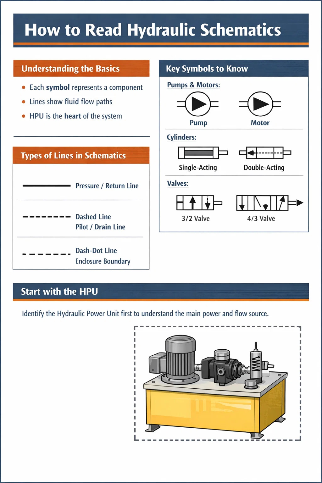
Reading hydraulic schematics is not as complicated as it looks. Once you understand that every symbol represents a physical component and every line represents a fluid path, the diagram starts to tell a clear mechanical story. The key is learning the ISO 1219 symbol library, understanding flow direction conventions, and recognizing how a Hydraulic Power Unit (HPU) anchors the entire circuit. Most technicians become proficient at reading standard schematics within a few weeks of focused practice.
This guide walks through everything from basic symbol recognition to reading complex multi-actuator circuits, with specific attention to the components you will encounter most often on industrial machinery, mobile equipment, and offshore systems. Whether you are a maintenance technician, a design engineer, or a machine operator trying to troubleshoot a fault, understanding how to read these diagrams is one of the most practical skills you can develop.
A hydraulic schematic is a symbolic diagram that shows how hydraulic components are connected and how fluid flows through a system. It does not show the physical location of components, their actual size, or the routing of pipes and hoses in space. What it does show is the logical relationship between components and the sequence or conditions under which fluid moves from one point to another.
Think of it like an electrical wiring diagram. A wiring diagram does not tell you where a wire physically runs through a wall, but it tells you exactly which terminal connects to which component and under what switching conditions current flows. A hydraulic schematic operates on the same logic, but for pressurized fluid instead of electricity.
Most hydraulic schematics follow ISO 1219-1 (Fluid Power Systems and Components — Graphic Symbols) or, in North America, ANSI/NFPA T3.25. The two standards share most symbols but differ in a few conventions. Industrial equipment sold globally will almost always use ISO 1219. Knowing which standard a schematic follows saves time when looking up unfamiliar symbols.
A crossing of two lines with no dot means the lines do not connect. A crossing with a filled dot means the lines do connect at that junction. This distinction matters significantly when tracing flow paths through complex circuits.
Hydraulic symbols are built from a small set of primitive shapes. Once you learn what each primitive shape means, you can decode symbols for components you have never seen before by reading the shape logic. The main primitives are circles, squares/rectangles, triangles, arrows, and arcs.
Both pumps and motors are represented by a circle. The difference is the direction of the filled triangle inside the circle. A triangle pointing away from the circle's center (outward) represents a pump — it pushes fluid out. A triangle pointing toward the center represents a motor — fluid enters and drives rotation. A variable-displacement version of either device will have a diagonal arrow drawn through the circle symbol.
In a Hydraulic Power Unit, you will typically see one or more pump symbols connected directly to a prime mover symbol (an electric motor represented by a circle with the letter M, or an engine symbol). The pump is the heart of the HPU — it converts mechanical energy into hydraulic flow, typically at pressures ranging from 150 bar to 350 bar in industrial systems.
A hydraulic cylinder is shown as a rectangle with a rod extending from one end. The rectangle represents the barrel, and the rectangle inside it (the piston) is usually implied by the port positions. A double-acting cylinder has two port lines — one on each side of the piston. A single-acting cylinder has one port line and often shows a spring symbol on the return side to indicate spring retraction.
Rotary actuators (hydraulic motors or oscillating actuators) are circles with bidirectional triangles and shaft lines. When you see curved arrows on a rotary actuator symbol, it indicates continuous rotation capability.
Valves are represented by squares. The number of squares in the symbol equals the number of switching positions the valve has. A two-position valve has two squares side by side. A three-position valve has three squares. The arrows and blocked-port symbols inside each square show the flow paths available in that position. The center square of a three-position valve shows the neutral or center condition, which is particularly important for understanding what happens when no signal is applied.
The actuator symbols attached to the outside of the valve envelope tell you how the valve shifts. Common actuators include:
A directional control valve described as "4/3 solenoid-operated, spring-centered" will show three squares with a solenoid on each outer square and a spring on each outer square. The center square will show the neutral flow condition — for example, all ports blocked (closed center), pressure to tank and both actuator ports blocked (tandem center), or all ports open (open center).
Relief valves, reducing valves, sequence valves, and counterbalance valves all appear as rectangles with a diagonal arrow and a spring, but their internal connections differ. A relief valve connects from the pressure line to tank and opens when pressure exceeds its set value — it is always shown in parallel with the circuit, protecting the system from overpressure. A pressure-reducing valve is placed in series in the line and limits the downstream pressure to a set value regardless of upstream conditions.
A check valve is shown as a ball or arrow against a seat — it passes flow in one direction only and blocks reverse flow. A pilot-operated check valve (POCV) adds a dashed pilot line to the check valve symbol, indicating that a pilot signal can override the check and allow reverse flow. POCVs are common in load-holding circuits where you need to lock a cylinder in position but also release it under controlled conditions.
A fixed restrictor is shown as a narrow constriction in the line. A variable flow control valve adds a diagonal arrow to indicate adjustability. A pressure-compensated flow control valve adds a rectangle with an internal arrow to show that the pressure drop across the restrictor is maintained constant — this ensures consistent flow rates regardless of load pressure variations, which is essential for consistent cylinder speeds.
The Hydraulic Power Unit is almost always shown as a distinct assembly enclosed in a dotted or dash-dot border on the schematic. This boundary tells you that everything inside is part of the HPU package — typically a reservoir, one or more pumps with prime movers, a main system relief valve, a suction strainer, a return line filter, and various instrumentation connections.
When reading a schematic that includes an HPU, start by identifying the boundary of the unit. Everything outside the boundary is field-installed circuit components. The connections passing through the HPU boundary are the interfaces between the power unit and the working circuit — typically a high-pressure supply port (labeled P or HP), a tank return port (labeled T or R), and often a drain port (labeled L or Dr) for internal leakage from motors and valves.
| Component | Symbol Feature | Function |
|---|---|---|
| Reservoir / Tank | Open rectangle at bottom of circuit | Stores hydraulic fluid and allows heat dissipation |
| Fixed-displacement pump | Circle with outward triangle, no diagonal arrow | Delivers constant flow per revolution |
| Variable-displacement pump | Circle with outward triangle and diagonal arrow | Adjustable flow output for energy efficiency |
| Main relief valve | Rectangle with diagonal arrow and spring, parallel to main line | Limits maximum system pressure |
| Suction strainer | Dashed line rectangle in suction line | Protects pump from large particle contamination |
| Return line filter | Solid rectangle with dashed internal symbol in return line | Removes fine contamination from returning fluid |
| Pressure gauge | Circle with needle pointer symbol | Local pressure reading for commissioning and diagnosis |
| Heat exchanger / cooler | Rectangle with arrows indicating cooling medium | Maintains fluid temperature within operating range |
A well-designed HPU schematic will also show the electric motor with its rated power and speed, the coupling between motor and pump, and any unloading valve or pressure-compensator control that manages the pump's standby behavior. In large industrial HPUs — units with pump outputs of 200 liters per minute or more — you will often see duplex pump arrangements with alternating duty/standby logic shown through a selector or changeover valve arrangement.
Approaching a schematic you have never seen before can be overwhelming if you try to read it all at once. The following process works reliably for schematics of any complexity level.
Before examining any symbol in detail, scan the entire schematic to understand its overall organization. Most schematics are drawn with the power source (the Hydraulic Power Unit or standalone pump assembly) on the left or at the top, with actuators (cylinders and motors) on the right or at the bottom. The main pressure supply line is typically at the top running horizontally, and the tank return line runs below it in parallel. Flow generally moves from left to right or top to bottom in normal operating conditions.
Note the title block — it will identify the machine, the drawing number, the revision level, and often the fluid type and nominal system pressure. This is critical context. A system designed for 250 bar with Tellus 46 mineral oil behaves very differently from a system designed for 420 bar with fire-resistant phosphate ester fluid.
Count and label every cylinder, hydraulic motor, and rotary actuator on the schematic. These are your outputs — the components that do the actual work. Understanding what work needs to be done gives you the context to understand why the valve and control circuitry is arranged the way it is. Each actuator will have a tag number or letter reference that ties back to the component list or bill of materials in the drawing package.
Follow the solid lines from the pump outlet all the way to each actuator and back to the tank. This trace reveals the physical path that pressurized fluid takes under normal operating conditions. Mark where branch points occur. At each branch, a check valve or flow divider is often present to manage priority between multiple circuits operating simultaneously.
For each directional control valve, identify: how many positions it has, what the flow path is in each position, how it is actuated (solenoid, pilot pressure, manual lever), and what its default/spring-return position is. The default position tells you what happens during a power failure or when no command signal is present — this is critical safety information for any machine.
A valve in the fail-safe closed (blocked center) condition will hold a load in place if power is lost. A valve in the fail-safe open (floating center) condition will allow a suspended load to drop. This distinction has significant safety implications and must be understood when reading schematics for lifting or support applications.
Follow the dashed lines throughout the schematic. These control signal lines often reveal the logic of the circuit — which valve controls which other valve, where sequence logic is built in, and where pressure feedback loops exist. Many schematics use pilot-operated directional valves where the pilot pressure comes from a separate pilot supply circuit drawn at reduced pressure (typically 30–50 bar) compared to the main working pressure.
Drain lines are also critical to trace. Components with internal leakage — variable pumps, hydraulic motors, some proportional valves — require a low-pressure drain line back to tank. If the drain line becomes blocked or develops back-pressure above about 5–10 bar, shaft seals will fail. The schematic shows you where these drain lines are and confirms they return to tank separately from the main return line.
Locate every relief valve on the schematic. The main system relief valve in the HPU sets the maximum allowable system pressure. Secondary relief valves on individual actuator circuits protect those specific circuits from load-induced pressure spikes. In a well-designed system, the main relief valve set pressure should be approximately 10–15% above the highest working pressure needed by any actuator in the system.
Hydraulic circuits are built from a relatively small number of recurring patterns. Recognizing these patterns on a schematic dramatically speeds up your reading and gives you immediate insight into the circuit's behavior.
Speed control of a cylinder or motor is achieved by restricting flow. In a meter-in circuit, the flow control valve is placed in the supply line to the actuator — it restricts how fast fluid enters the actuator. In a meter-out circuit, the flow control valve is placed in the return line — it restricts how fast fluid leaves the actuator. Meter-out is preferred for overrunning load applications because it maintains positive back-pressure that prevents the load from running away faster than the pump is supplying fluid.
A bleed-off circuit places the flow control valve in a branch line that diverts some pump flow directly to tank, rather than putting it in the actuator supply or return line. This is more energy-efficient because excess flow bypasses the actuator at lower pressure, but it provides less precise speed control under varying loads.
A regenerative circuit appears on a schematic as a connection between the rod-end port of a cylinder and the cap-end supply line. When the directional control valve is shifted to extend the cylinder, the rod-end return flow is routed back to the cap end rather than to tank. This increases extension speed because the effective flow to the cap end equals pump flow plus return flow from the rod side. The trade-off is reduced force capacity during the regenerative stroke. Regenerative circuits are used in press approach phases, slide applications, and any situation where rapid traverse before full-force contact is needed.
When a schematic shows a counterbalance valve on the rod-end port of a vertically-mounted cylinder, the circuit is designed to prevent the load from descending under gravity when the directional valve is in neutral or when a line ruptures. The counterbalance valve requires a pilot signal from the supply side to open, meaning the load can only lower when the pump is actively supplying pressure — the load cannot freefall even if a hose fails between the valve manifold and the cylinder. Counterbalance valve set pressure is typically 1.3 times the maximum load-induced pressure to prevent chatter while still allowing controlled lowering.
An accumulator symbol (a circle divided by a curved line representing the separator membrane or bladder) indicates energy storage in the circuit. Accumulators serve several purposes — they can supply high instantaneous flow for short-duration actuations without requiring a large pump, they can maintain system pressure during pump idle periods, and they dampen pressure spikes. When you see an accumulator on a schematic, also look for a safety unloading valve or dump valve circuit that allows the stored pressure to be released to tank before any maintenance work — this is a mandatory safety feature in any accumulted hydraulic circuit.
Proportional valves and servo valves appear on schematics as directional control valve symbols with additional detail indicating continuous variable positioning rather than discrete switching. A proportional directional valve is often drawn as a standard directional valve symbol with a proportional solenoid indicated by a symbol showing a variable spring or a symbol annotated with "proportional" or "PROP" in the tag. A servo valve is drawn similarly but often with a torque motor symbol and internal feedback path indicating closed-loop spool position control.
Circuits using these valves are typically closed-loop position or velocity control systems. The schematic will show feedback sensors — linear position transducers (LVDTs), rotary encoders, or pressure transducers — with signal lines going back to a controller block. These signal lines are usually shown as thin lines or annotated as electrical signals rather than hydraulic lines. Understanding which signals are hydraulic and which are electrical is important when reading these more complex schematics. The controller block may be shown as a simple rectangle with labeled inputs and outputs, with the detailed electrical schematic on a separate drawing set.
The Hydraulic Power Unit supplying servo valve circuits must provide exceptionally clean fluid — typically ISO 4406 cleanliness class 16/14/11 or better — because servo valves have internal clearances of 2–5 microns and are extremely sensitive to particulate contamination. The HPU schematic for servo systems will show high-efficiency pressure filters (rated at 3–10 micron absolute) in addition to the standard return line filter.
Every component on a professional hydraulic schematic is tagged with an alphanumeric reference, such as V1, V2, CV3, RV1, CYL-A, or M1. These tags correspond to a component list (also called a bill of materials or parts list) that appears either in the title block area of the drawing or on a separate document. The component list gives you the manufacturer, model number, and key specifications for each tagged component.
For troubleshooting, the tag number is your most efficient path to finding the datasheet for a specific component. If the schematic shows that valve V3 should be shifting when solenoid Y3 is energized but the cylinder is not moving, you look up V3 in the component list to find the exact valve model, then retrieve the datasheet to check electrical coil specifications, spool configuration options, and minimum operating pressure requirements.
The most practical use of hydraulic schematics in day-to-day work is fault diagnosis. A schematic gives you a logical map of the system that allows you to systematically isolate a fault rather than guessing or swapping parts at random. Experienced hydraulic technicians use a process called "half-splitting" — using the schematic to identify the midpoint of a suspect circuit and testing there first, then eliminating half the circuit as the fault source with each test.
Using the schematic, trace the flow path that should exist when the extend command is given. Starting at the HPU, check that system pressure is present. Follow the line to the directional control valve — is the solenoid being energized (check the electrical schematic for the control signal)? If the solenoid is confirmed energized, is the valve shifting (pressure should appear at the cap-end port of the cylinder per the schematic)? If pressure appears at the cap end but the cylinder does not move, the issue is likely on the return side — a blocked return path, a seized counterbalance valve, or a failed cylinder seal that is bypassing fluid from cap end to rod end internally.
Every one of these diagnostic steps requires you to know exactly what the schematic shows should be happening at each point. Without the schematic, you are testing blind.
When a hydraulic system develops contamination-related problems, the schematic helps you understand which components are most at risk. Proportional and servo valves with fine internal clearances will fail first. Filter indicators — shown on the schematic as pressure differential indicators across filter elements — will trigger earlier than usual. The schematic shows you the cleanliness-critical components (typically those with internal clearances under 10 microns) so you know where to focus inspection when contamination is suspected.
During initial commissioning of a system, the schematic is used to verify that every valve is in the correct configuration, every pressure setting is correct, and every flow path functions as designed. A systematic approach involves checking each relief valve by creating the load condition described in the commissioning procedure and confirming the system reaches the specified relief pressure — typically using a calibrated test gauge at the test point shown on the schematic. The HPU is usually commissioned first in isolation, confirming pump output pressure and flow, before the field-mounted circuit components are activated.
A simple single-cylinder schematic might have fewer than 20 components and fit on a single A3 sheet. A complex multi-actuator system — such as a large press with 12 cylinders, multiple speed stages, and simultaneous load-holding requirements — can run to 10 or more drawing sheets with hundreds of components. The reading approach scales accordingly.
For multi-sheet schematics, each sheet typically covers one functional zone of the machine, with cross-references showing where a line from one sheet connects to a line on another sheet. These cross-references are shown as triangular or circular flags with a sheet number and line reference — for example, "→ SH3/L12" meaning the line continues on sheet 3 at line 12. Always follow these cross-references when tracing a flow path, rather than assuming a line that terminates at a flag is a dead end.
Large schematics for multi-actuator systems often include a function table or truth table showing which solenoids are energized in each machine operating mode. This table is enormously useful for understanding the system logic without having to mentally trace every valve state for every operating condition. If such a table is included, read it alongside the schematic — it condenses the circuit logic into an easily scannable format.
Reading hydraulic schematics fluently is a skill built through repeated exposure to real diagrams, not just memorization of symbol tables. The following habits will accelerate your development significantly.
Most professional hydraulic engineers reach a level of comfortable schematic literacy within 3–6 months of regular exposure to real system documentation. Maintenance technicians who work with the same machine type daily can become very fast readers of that specific schematic style within 4–8 weeks. The key is consistent, active engagement with real diagrams rather than passive review of symbol charts.

This hydraulic power unit is specially designed for dump trailers. It is integrated by a high-pressure gear pump, DC carbon brush machine, central val...
See Details
This hydraulic pump station is composed of a series of side inlet and side outlet gear pumps and 4.5 or 5-inch DC motors. It is often used as a hydrau...
See Details
This DC micro power unit combines high-pressure gear pumps, DC motors, center valve blocks, cartridge valves and oil tanks. It is compact and powerful...
See Details
This hydraulic power unit is designed for scissor lifts and integrates a high-pressure gear pump, AC motor, center valve block, cartridge valve and oi...
See Details
This hydraulic power unit is specially designed for the clamping cylinder of the machine, too. It is integrated by a high-pressure gear pump.AC motor,...
See Details
This hydraulic power unit is specially designed for hot-melt butt welding machine and is integrated by high-pressure gear pump, AC motor central valve...
See Details
This hydraulic power unit is specially designed for hydraulic cargo elevators and is integrated with a high-pressure vane pump, AC Oil immersion motor...
See Details
The multi-connection hydraulic integrated valve block is an efficient integrated component of the hydraulic system, including two-connection, three-co...
See Details
The relief valve is the core component for controlling pressure in the hydraulic system. It can maintain the stability of the system pressure and prev...
See Details
The cartridge hydraulic control check valve controls the on/off and flow direction of the hydraulic oil to start, stop, change direction and lock the ...
See Details
No. 12 Tongji Road, Simen Town, Yuyao City

+86-0574-62130352
+86-18905846028

+86-0574-62130353

Copyright© Ningbo Panic Hydraulic Technology Co., Ltd. All Rights Reserved. China Hydraulic Power Units Manufacturers
