


 English
 中文简体
中文简体 русский
Lifting platform power unit
Cat:AC series hydraulic power unit
Designed for hydraulic lifting platforms, this lifting platform power unit integrates a high-pressure gear pump, AC motor, center valve block, cartrid...
See DetailsContent
A hydraulic pump lasts longest when three things happen on schedule and without exception: fluid stays clean to at least ISO 4406 18/16/13 for most industrial systems, operating temperature stays under 180 degrees Fahrenheit (82 degrees Celsius), and inlet pressure never drops low enough to allow cavitation. Skip any one of these and the pump will fail early, usually inside two years instead of the eight to twelve years a well maintained unit can deliver. That is the short version. The rest of this guide breaks down exactly how to build a maintenance program around those three pillars, what a proper hydraulic pump station maintenance routine looks like on paper, how to read the early warning signs before a pump seizes, what the real cost difference is between reactive repair and planned upkeep, and how different pump types change the maintenance approach.
Hydraulic pump maintenance is not a single task, it is a layered discipline that spans daily visual checks, weekly fluid sampling, monthly component inspection, and annual teardown or overhaul depending on duty cycle. A hydraulic pump station, which bundles the pump, reservoir, motor, valves, filtration, and cooling into one integrated skid, adds an extra layer because every component in that station affects the health of every other component. A dirty filter on the station raises pump wear. A weak cooler raises fluid temperature and accelerates seal degradation. A loose motor coupling introduces vibration that fatigues the pump shaft. None of these failures happen in isolation, which is exactly why maintenance has to be planned as a system rather than as a checklist for the pump alone.
Facilities that treat hydraulic pump maintenance as an afterthought tend to discover the cost of that decision at the worst possible moment, usually mid production run when a pump seizes without warning. Facilities that treat it as a planned discipline, with documented intervals, trend tracking, and a defined escalation path when readings drift outside normal range, consistently report fewer unplanned stoppages and a lower total cost of ownership across the equipment's working life. The difference between those two outcomes rarely comes down to budget. It comes down to whether the maintenance plan is written down, followed consistently, and adjusted based on real data rather than guesswork.
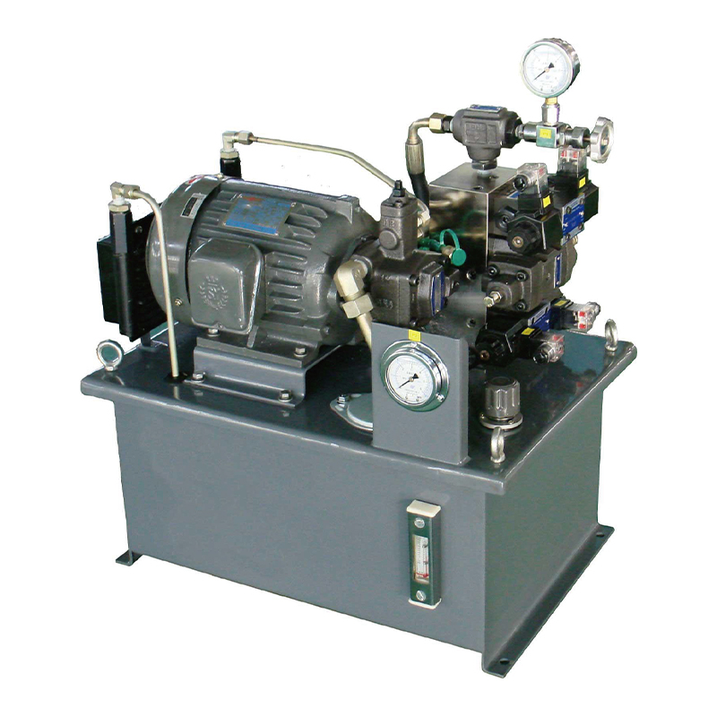
Most pump failures announce themselves weeks or months before the actual breakdown. The technicians who catch these signals early are the ones who schedule a planned repair over a weekend instead of dealing with an unplanned shutdown during a production run. Here are the signals worth tracking on every hydraulic pump and every hydraulic pump station in a facility.
A whining or knocking sound, often described by operators as marbles in a tin can, is the classic symptom of cavitation. It happens when the pump cannot draw enough fluid to fill the pump chamber, usually because of a restricted suction line, a collapsed hose, or fluid that is too cold and too viscous to flow properly. Left unaddressed, cavitation erodes the pump internals within days, not months.
Every 18 degrees Fahrenheit rise above the optimal operating band cuts hydraulic fluid life roughly in half, based on the Arrhenius reaction rate rule widely applied in lubricant chemistry. A pump running consistently hot is either working harder than it should because of internal wear, or the station's cooling capacity has fallen behind the heat load.
When a cylinder that used to extend in four seconds now takes six, internal leakage across worn pump components is very often the cause. Volumetric efficiency drops as clearances open up between the gears, vanes, or pistons and their housings, so more of the pump's output recirculates internally instead of doing work.
A used oil analysis report showing rising iron, bronze, or aluminum particle counts is one of the most reliable predictors of pump wear, often visible in lab data eight to twelve weeks before a pump shows any external symptom at all.
A pump or motor coupling that vibrates more than it did during commissioning usually means misalignment, a worn bearing, or an unbalanced coupling. Left running, that vibration fatigues the pump shaft seal first, then the shaft itself.
A system pressure gauge that used to sit steady but now flickers or slowly drifts down under load points to either a failing relief valve or a pump that can no longer maintain its rated output, both of which call for immediate inspection.
Fluid that looks foamy at the reservoir sight glass usually means air entrainment somewhere in the suction or return circuit. Fluid that looks milky or cloudy points to water contamination, which accelerates additive breakdown and encourages internal corrosion on pump components.
A drive motor pulling noticeably more current than its baseline reading, at the same load and speed, often signals internal pump drag from worn bearings, a bent shaft, or debris lodged inside the pumping chamber restricting free rotation.
None of these signs on their own is proof of imminent failure, but two or more appearing together, especially rising temperature paired with slower cycle times, should move an inspection from the next scheduled interval to the current week. Waiting for a single dramatic symptom, like a sudden total loss of pressure, almost always means the window for a controlled, planned repair has already closed.
The schedule below reflects what most equipment builders recommend for medium duty industrial hydraulic pumps and hydraulic pump stations running one to two shifts a day. Pumps in continuous three shift operation, mobile equipment, or dusty environments should shift every interval down one tier, meaning monthly tasks move to biweekly and so on.
| Interval | Task | What To Check |
|---|---|---|
| Daily | Visual and audible inspection | Fluid level, leaks at fittings and shaft seal, abnormal noise, gauge readings against baseline |
| Weekly | Filter indicator check | Bypass indicator status, differential pressure across filters, reservoir breather cap condition |
| Monthly | Fluid sampling | Particle count against ISO 4406, water content, viscosity, additive depletion |
| Quarterly | Mechanical inspection | Coupling alignment, mounting bolt torque, hose and fitting condition, cooler fin cleanliness |
| Semiannually | Performance verification | Flow output test against rated capacity, relief valve crack pressure, cylinder cycle timing |
| Annually | Component overhaul review | Shaft seal replacement, bearing condition, internal clearance measurement, relief valve recalibration |
Facilities that adopt this tiered schedule and actually follow the fluid sampling interval typically report pump life extending by 40 to 60 percent compared with facilities that only react to visible leaks or noise, a pattern consistently documented in fluid power industry maintenance case studies and reliability engineering literature.
Assigning clear ownership for each interval matters as much as the interval itself. Daily checks are best handled by machine operators who already interact with the equipment every shift and can flag anything unusual before it becomes a work order. Weekly and monthly tasks typically fall to a maintenance technician with fluid sampling training. Quarterly and annual tasks often justify bringing in a specialist familiar with the specific pump type, especially for internal clearance measurement, which requires precision tools and experience interpreting the results correctly.
| Interval | Typical Owner | Documentation Needed |
|---|---|---|
| Daily | Machine operator | Shift log entry noting any deviation from baseline |
| Weekly / Monthly | Maintenance technician | Filter change log, fluid sample lab report, trend chart update |
| Quarterly / Annually | Specialist or original equipment manufacturer service team | Alignment reading, torque values, teardown inspection report |

A hydraulic pump station is more than a pump bolted to a tank. It is an integrated assembly of reservoir, motor, coupling, pump, directional and relief valves, filtration, cooling, and often a control panel with pressure and temperature sensors. Maintaining a hydraulic pump station properly means treating the whole skid as one interdependent system rather than servicing the pump in isolation.
The reservoir deserves more attention than it usually gets. Sediment settles at the bottom of the tank over months of operation, and if the return line dumps fluid directly above the suction line, that sediment gets pulled straight back into the pump. A baffle plate positioned correctly inside the reservoir, along with a suction strainer sized for the pump's flow rate, prevents this short-circuiting effect and keeps particulate away from the pump inlet.
The motor-to-pump coupling is another area specific to the station configuration. Flexible couplings compensate for minor misalignment, but they are not designed to correct for gross misalignment from a poorly installed motor base. A dial indicator check of angular and parallel alignment during commissioning, and again after any motor replacement, prevents the single most common cause of premature pump shaft seal failure on new station installations.
Reservoir sizing also plays a larger role in station reliability than most specification sheets suggest. A reservoir that is too small for the pump's flow rate does not give fluid enough dwell time to release entrained air or settle particulate before being pulled back through the suction line, which means the pump is constantly working with fluid that is not fully conditioned. A commonly referenced sizing guideline is a reservoir volume of three to five times the pump's rated flow per minute, though systems with high heat loads or aggressive cycle rates often benefit from sizing toward the higher end of that range.
Control panel instrumentation, when present on a station, is only useful if it stays calibrated. A pressure transducer or temperature sensor that has drifted out of calibration can mask a developing problem for months, showing readings that look normal while the actual pump condition deteriorates. Annual calibration against a known reference gauge, cross-checked at commissioning and then yearly afterward, keeps the instrumentation trustworthy enough to actually catch early warning signs rather than simply displaying numbers nobody fully trusts.
Gear pumps, vane pumps, and piston pumps all move hydraulic fluid, but they wear differently and therefore need slightly different maintenance attention. Applying a piston pump maintenance mindset to a gear pump, or the reverse, tends to either waste effort checking things that rarely matter for that design or miss the specific failure mode that design is actually prone to.
| Pump Type | Primary Wear Point | Maintenance Priority |
|---|---|---|
| Gear pump | Gear tooth face and side plate wear | Fluid cleanliness, since gear pumps are highly sensitive to particulate contamination |
| Vane pump | Vane tips and cam ring surface | Correct viscosity and cleanliness, plus checking for vane sticking from varnish buildup |
| Axial piston pump | Piston shoes, swash plate, and valve plate | Case drain flow monitoring and fluid cleanliness at a tighter ISO target |
| Radial piston pump | Cylinder bore and piston ring wear | Inlet pressure and cavitation avoidance, since these pumps are sensitive to starvation |
Piston pumps in particular reward close attention to case drain flow, since a rising case drain rate at constant operating pressure is one of the earliest and most reliable indicators of internal wear across piston shoes and the valve plate. Many piston pump manufacturers publish a maximum acceptable case drain flow rate for a given displacement and pressure, and comparing actual readings against that published figure on a quarterly basis catches wear trends well before performance loss becomes noticeable to an operator running the machine.
Contamination is responsible for the majority of hydraulic pump failures across nearly every industry survey conducted by fluid power associations over the past two decades, with figures commonly cited between 70 and 85 percent of all failures traced back to particulate or water contamination in the fluid. Understanding where contamination enters the system is more useful than simply filtering after the fact.
Beyond contamination, the second most common root cause is aeration, which is different from cavitation though the two are often confused. Aeration happens when air is entrained into the fluid, typically through a loose suction fitting, a return line that splashes above the fluid surface, or a fluid level that has dropped low enough to expose the suction line intermittently. Aerated fluid compresses under pressure instead of transmitting force cleanly, which produces spongy cylinder movement, overheating, and accelerated pump wear from the resulting micro-cavitation inside the pump chamber itself.
A third recurring cause is simply operating a pump outside its designed envelope, whether that means running at a pressure above the rated maximum, running at a speed the pump was not designed for, or running with a fluid viscosity far outside the manufacturer's acceptable range. Each of these conditions individually might not cause immediate failure, but they compound the wear rate substantially when combined with even moderate contamination, which is why two facilities running what looks like the identical pump can see very different service life depending on how closely each one holds to the manufacturer's operating envelope.
A fourth cause, less discussed but increasingly common as facilities push equipment harder, is thermal cycling fatigue. A pump that starts cold every morning, heats rapidly under load, and then cools completely overnight experiences repeated expansion and contraction across its internal components. Over years of daily cycling, this thermal stress contributes to seal hardening and can loosen press-fit components that were originally installed with proper interference, even without any single event that would show up as an obvious failure cause on a work order.
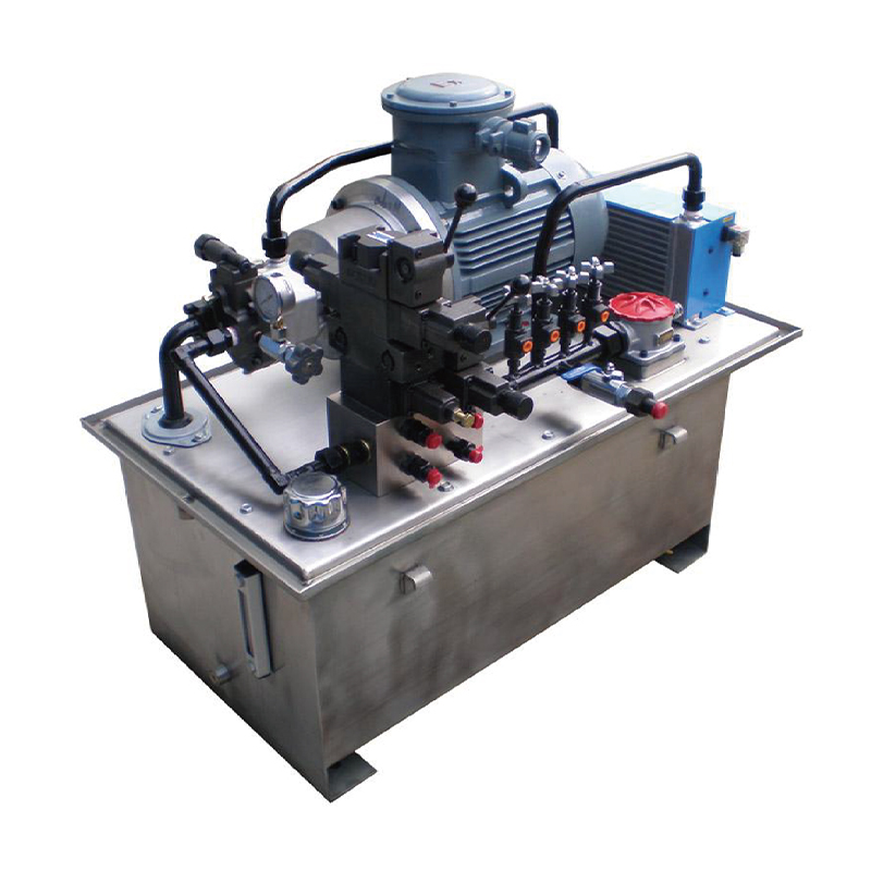
Filter new fluid before it ever enters the reservoir, even fluid straight from a sealed drum. Manufacturing and shipping introduce particulate that factory cleanliness ratings do not always reflect by the time fluid reaches a facility.
Size the cooler for worst case ambient conditions, not average conditions. A cooler that keeps fluid at target temperature on a mild day but lets it climb 20 degrees on a hot summer afternoon is undersized for the application.
A vane pump and a piston pump often specify different viscosity grades even in the same system, and cold start conditions in unheated facilities can push viscosity well outside the pump manufacturer's acceptable range at startup.
Loose pump mounting bolts introduce vibration that fatigues the shaft over time, while overtightened bolts can distort the pump housing enough to change internal clearances. Both directions of error shorten pump life.
A single oil sample tells you the current state. A trend across six consecutive monthly samples tells you the rate of wear, which is what actually predicts remaining pump life and lets a maintenance team schedule a rebuild before an unplanned failure.
Running a cold system straight to full pressure forces the pump to work against fluid that is far more viscous than its design point, increasing internal friction and load on the shaft seal until the fluid reaches a reasonable operating temperature. A short warm-up cycle at reduced load protects the pump every single startup.
Using a single approved fluid specification across as much compatible equipment as possible reduces the chance of cross-contamination from mixing incompatible additive packages, and it simplifies inventory management enough that technicians are less likely to grab the wrong drum during a top-off.
A work order that says seal replaced tells a future technician nothing useful. A work order that says seal replaced due to misalignment measured at 0.015 inch, corrected during reinstall, gives the next person facing a similar failure a genuine head start on diagnosis.
ISO 4406 cleanliness codes describe the number of particles in three size ranges per milliliter of fluid, commonly written as three numbers such as 18/16/13. Lower numbers mean cleaner fluid. Most industrial hydraulic pumps specify a target cleanliness level, and running fluid two or three codes dirtier than that target can cut pump life by half or more according to bearing and pump manufacturer wear life data that correlates directly with particle count.
Water content deserves separate attention from particulate. Even small amounts of dissolved water, often below levels visible to the naked eye, accelerate additive depletion and can cause micro-pitting on pump internals through a process similar to electrical discharge. A fluid sample that looks clear can still carry enough dissolved water to shorten pump component life, which is exactly why lab analysis rather than visual inspection is the only reliable way to confirm fluid condition.
Viscosity index and additive depletion round out the core fluid analysis picture alongside particle count and water content. Viscosity that has drifted more than roughly ten percent from the fluid's rated value, in either direction, signals either thermal breakdown of the base oil or contamination from an incompatible fluid mixed in during a top-off. Additive depletion, tracked through measurements such as the acid number and the remaining anti-wear additive concentration, indicates how much useful life remains in the current fluid charge even if particle count and water content both look acceptable.
| Parameter | What It Measures | What A Bad Reading Suggests |
|---|---|---|
| Particle count | Solid contaminant concentration by size | Filtration gap, internal wear generating debris, or breach in a seal |
| Water content | Moisture percentage in the fluid | Condensation, breather failure, or cooler leak allowing coolant ingress |
| Viscosity | Fluid thickness at a reference temperature | Thermal breakdown, wrong fluid topped off, or extreme operating temperature |
| Acid number | Oxidation and additive depletion level | Fluid nearing end of useful service life |
A well run fluid analysis program does not stop at receiving the lab report. The real value comes from plotting each parameter on a trend chart across consecutive sampling periods, since a single reading only shows a snapshot while a trend line reveals the rate at which the fluid and the pump are wearing. A facility that reviews these trends monthly, and has a documented threshold for when a reading triggers an inspection rather than simply another sample, converts fluid analysis from a paperwork exercise into a genuine predictive maintenance tool.
The rotary shaft seal is usually the first component to fail on a hydraulic pump, and it fails for predictable reasons: excessive case drain pressure, shaft misalignment from the coupling, or simple age hardening of the seal material after years of heat cycling. Replacing a shaft seal proactively at the interval a manufacturer recommends is far less expensive than replacing the seal, the shaft, and the housing after a seal failure allows fluid to leak into the bearing and destroy it as well.
Pump bearings wear from three primary causes: fluid contamination working its way past the seal, excessive side load from belt drives or misaligned couplings, and simple fatigue at the end of their rated life. A bearing that shows any play when the shaft is gently rocked by hand, checked with the pump depressurized and locked out, should be scheduled for replacement rather than run to failure.
The coupling connecting motor to pump absorbs any residual misalignment left after installation, and different coupling designs tolerate that misalignment differently. Elastomeric spider couplings tolerate minor misalignment well but degrade with age and heat, developing play that shows up as backlash and vibration long before the coupling visibly cracks. Inspecting the coupling insert annually, and replacing it proactively rather than waiting for visible cracking, protects both the pump shaft seal and the bearings from the vibration a worn coupling introduces.
When a shaft seal does need replacement, the condition of the shaft surface itself matters as much as the new seal. A shaft that has developed a wear groove at the seal contact point, often from years of a slightly hardened original seal riding in one spot, will cause a brand new seal to leak again within a short time unless the shaft is either polished smooth, fitted with a speedi-sleeve repair collar, or replaced outright. Skipping this step is one of the most common reasons a seal replacement fails to solve a leak problem permanently.
| Symptom | Likely Cause | First Diagnostic Step |
|---|---|---|
| Loud whining noise | Cavitation from restricted suction | Check suction line for kinks, clogged strainer, or low fluid level |
| Pump runs but no pressure builds | Internal wear or stuck relief valve | Isolate relief valve and retest, then check pump case drain flow |
| Fluid leaking at shaft | Worn or hardened shaft seal | Inspect case drain pressure and coupling alignment before replacing seal |
| Overheating fluid | Undersized cooling or internal slippage | Compare current fluid temperature against baseline commissioning data |
| Slow or erratic cylinder movement | Volumetric efficiency loss | Measure actual flow output against rated flow at operating pressure |
| Pump will not start or stalls | Seized internal components or motor overload | Check motor amperage draw and rotate shaft by hand if depressurized and locked out |
| Chattering or shuddering under load | Air trapped in the system or a sticking relief valve | Bleed high points in the circuit and inspect relief valve for sticking spool |
| Fluid discolored or smells burnt | Thermal breakdown from sustained overheating | Send a fluid sample for lab analysis and inspect cooler performance |
When a new symptom appears, resist the urge to jump straight to replacing the pump. Most of the symptoms above trace back to something upstream or downstream of the pump itself, such as a clogged filter, a failing cooler, or a misaligned coupling, all of which are far less expensive to correct than an unnecessary pump replacement. A short, methodical diagnostic sequence, starting with the cheapest and easiest checks first, usually identifies the true root cause faster than guessing based on the most dramatic symptom.

Beyond manual inspection and periodic fluid sampling, a growing number of facilities now install continuous condition monitoring on critical hydraulic pumps and pump stations. Inline particle counters provide a live cleanliness reading rather than waiting for a monthly lab sample, catching a sudden contamination event, such as a seal failure elsewhere in the circuit, within hours instead of weeks. Vibration sensors mounted on the pump housing or motor bearing can detect the earliest stages of bearing wear or misalignment well before the vibration becomes audible or noticeable by hand.
Temperature and pressure sensors feeding into a facility's control system allow trend charts to be built automatically rather than relying on a technician manually logging gauge readings, which both improves data consistency and frees up technician time for actual inspection and repair work rather than data collection. For facilities running critical equipment where unplanned downtime carries a high cost, the investment in continuous monitoring hardware typically pays for itself within the first prevented unplanned failure.
None of this technology replaces the fundamentals covered earlier in this guide. Continuous monitoring simply catches deviations faster and with less manual labor, but the underlying maintenance practices, clean fluid, correct temperature, proper alignment, and disciplined documentation, remain exactly the same regardless of how the readings are collected.
A well planned spare parts strategy shortens repair time dramatically when a pump does need service. Keeping a shaft seal kit, a filter element, and a set of gaskets on hand for every critical pump in a facility means a routine repair does not turn into an extended shutdown waiting for parts to ship. For pumps supporting a critical production line, many facilities go a step further and keep a fully rebuilt spare pump ready to swap in, minimizing downtime to the time it takes to disconnect and reconnect fittings rather than the time it takes to actually rebuild the failed unit.
Documentation ties directly into parts strategy. A maintenance file for each pump that records the original commissioning data, every fluid analysis report, every repair performed with its root cause, and the current spare parts on hand gives any technician, including one unfamiliar with that specific machine, the context needed to diagnose a problem quickly rather than starting from scratch. Facilities that maintain this kind of documentation consistently resolve repeat failures faster than facilities relying on individual technician memory, since the pattern behind a recurring problem becomes visible in the written record even when the technician who diagnosed it the first time is unavailable.
Facilities that track total maintenance spending typically find that a planned hydraulic pump rebuild, done on schedule with the machine down for a planned window, costs a fraction of an emergency replacement that includes rush parts shipping, overtime labor, and lost production during unplanned downtime. Reliability studies across manufacturing sectors have repeatedly found unplanned downtime costs running three to five times higher than the equivalent planned maintenance cost once lost production, expedited freight, and overtime labor are all factored in.
A hydraulic pump station that fails during a production run does not just cost the price of the pump. It costs the downstream equipment sitting idle, the labor standing by unable to work, and in many cases scrapped material caught mid-cycle when hydraulic pressure disappeared unexpectedly. Building a maintenance budget around scheduled component replacement, informed by the fluid analysis trends discussed earlier, consistently proves cheaper across a five to ten year equipment lifespan than a run-to-failure approach, even though the up-front planned maintenance spending looks larger on a month to month basis.
There is also a less visible cost worth accounting for, which is the wear a struggling pump inflicts on the rest of the hydraulic circuit before it finally fails outright. A pump running with reduced volumetric efficiency forces the rest of the system to compensate, often through higher cycle times, increased heat generation across the whole circuit, and additional strain on valves and cylinders working against a less consistent flow supply. By the time such a pump is finally replaced, it is common to find accelerated wear on components elsewhere in the system that would not have needed attention had the pump been serviced earlier.
Most industrial systems change fluid based on condition rather than a fixed calendar interval, guided by the monthly fluid analysis results. As a general reference point, many facilities plan a full fluid change somewhere between 2,000 and 4,000 operating hours, but a system with excellent filtration and cool operating temperatures can extend well beyond that, while a system running hot or in a dusty environment may need fluid changed sooner.
A well maintained industrial hydraulic pump commonly reaches 8 to 12 years or 15,000 to 20,000 operating hours before a major overhaul is needed, though this varies significantly with duty cycle, fluid cleanliness, and operating temperature. Pumps running in poorly filtered systems or at elevated temperatures can fail in under two years.
Some stations in consistently cold ambient conditions run without active cooling, relying on reservoir surface area and ambient air for heat dissipation, but this depends entirely on duty cycle and load. A station under continuous high load will generate more heat than passive cooling can dissipate regardless of ambient temperature.
Gradual pressure loss is almost always internal wear increasing clearances between moving components, which increases internal leakage and lowers volumetric efficiency over time. This differs from sudden pressure loss, which more often points to a mechanical failure such as a broken shaft, a seized component, or a relief valve stuck open.
Rebuilding is often the more economical choice when the pump housing and shaft are still within tolerance, since the housing typically represents a significant portion of total pump cost. A rebuild replacing seals, bearings, and worn internal components can restore a pump close to original performance at a meaningfully lower cost than a full replacement unit.
The most reliable way is a fluid analysis report comparing actual ISO cleanliness code against the pump manufacturer's target code. If the fluid consistently tests two or more codes dirtier than target, filtration capacity, filter micron rating, or filter placement in the circuit likely needs to be reevaluated rather than simply changing filter elements more often.
Yes. Gear pumps are especially sensitive to fluid cleanliness since particulate directly scores the gear teeth and side plates, while piston pumps benefit most from close monitoring of case drain flow, which reveals internal wear across the piston shoes and valve plate well before an obvious performance drop appears.
Case drain flow is the small amount of fluid that leaks internally past pump components and drains back to the reservoir through a dedicated case drain line rather than doing useful work. A rising case drain flow rate at the same operating pressure is one of the earliest and most measurable signs of internal pump wear, particularly on piston pumps.
Whether redundancy makes sense depends on how costly downtime is for the specific application. Facilities running continuous, high value production often justify a standby pump on the same station, automatically switched in on a pressure drop, since the cost of the extra pump is small compared with even a single hour of unplanned production loss.
Severe contamination, such as a sudden ingress of coarse particulate from a failed filter or a torn seal elsewhere in the circuit, can visibly score pump internals within hours of continuous operation. Chronic low level contamination works more slowly, typically shortening service life over months rather than causing immediate damage, which is why trend based fluid analysis catches it long before a sudden failure would.

Designed for hydraulic lifting platforms, this lifting platform power unit integrates a high-pressure gear pump, AC motor, center valve block, cartrid...
See Details
This hydraulic power unit is specially designed for the clamping cylinder of the machine, too. It is integrated by a high-pressure gear pump.AC motor,...
See Details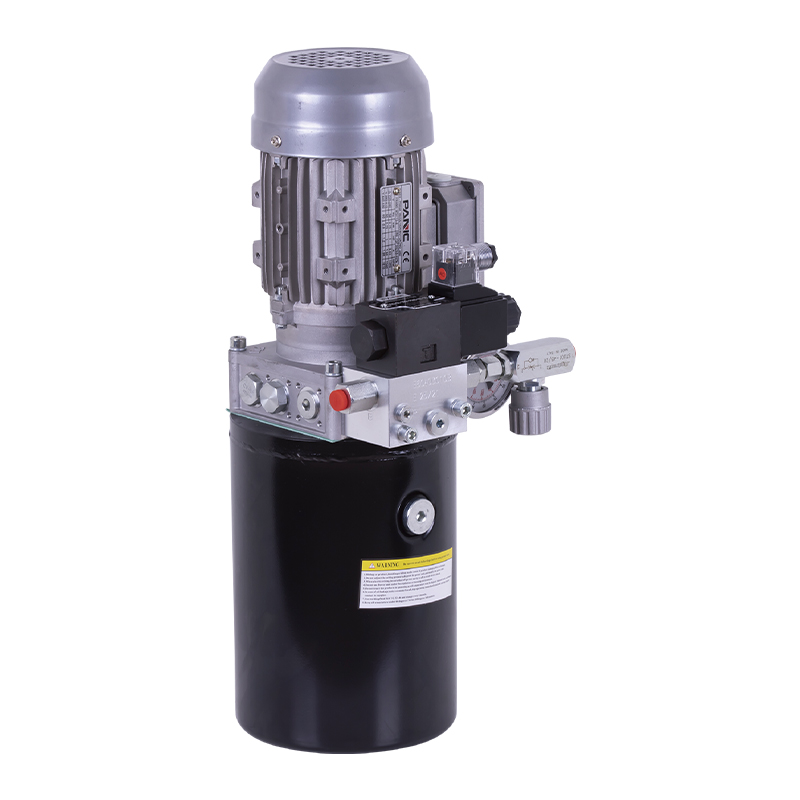
This hydraulic power unit is specially designed for the rotary feed of the pipe cutting machine. It is integrated by a high-pressure gear pump, an AC ...
See Details
This hydraulic power unit is specially designed for the storage flushing door and is integrated with a high-pressure gear pump, AC motor, central valv...
See Details
The hydraulic power unit is specially designed for the integrated hydraulic lifting column, which is integrated by a two-way gear pump, an AC oil imme...
See Details
This hydraulic power unit is specially designed for a split hydraulic lifting column, It integrates a bidirectional gear pump, AC oil-immersed motor, ...
See Details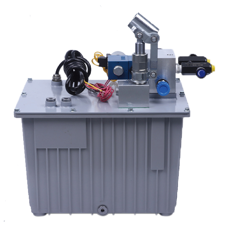
This hydraulic power unit is specially designed for an anti-terrorism hydraulic roadblock machine. It is integrated by a high-pressure gear pump, an A...
See Details
The V3068 hydraulic valve group is an electric check valve group designed for hydraulic systems. It is mainly used to prevent the backflow of media, e...
See Details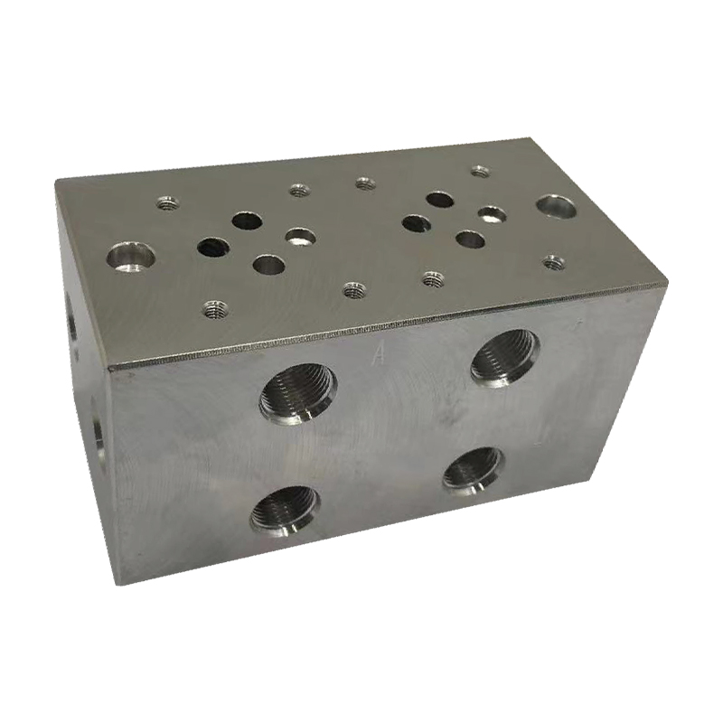
The multi-connection hydraulic integrated valve block is an efficient integrated component of the hydraulic system, including two-connection, three-co...
See Details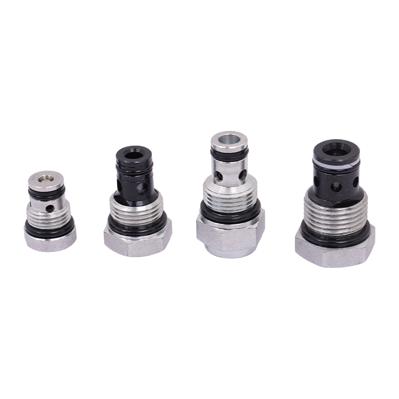
The power unit check valve (also called non-return valve) is a key component for controlling the one-way flow of fluids. It can prevent hydraulic oil,...
See Details
No. 12 Tongji Road, Simen Town, Yuyao City

+86-0574-62130352
+86-18905846028

+86-0574-62130353

Copyright© Ningbo Panic Hydraulic Technology Co., Ltd. All Rights Reserved. China Hydraulic Power Units Manufacturers

