


 English
 中文简体
中文简体 русский
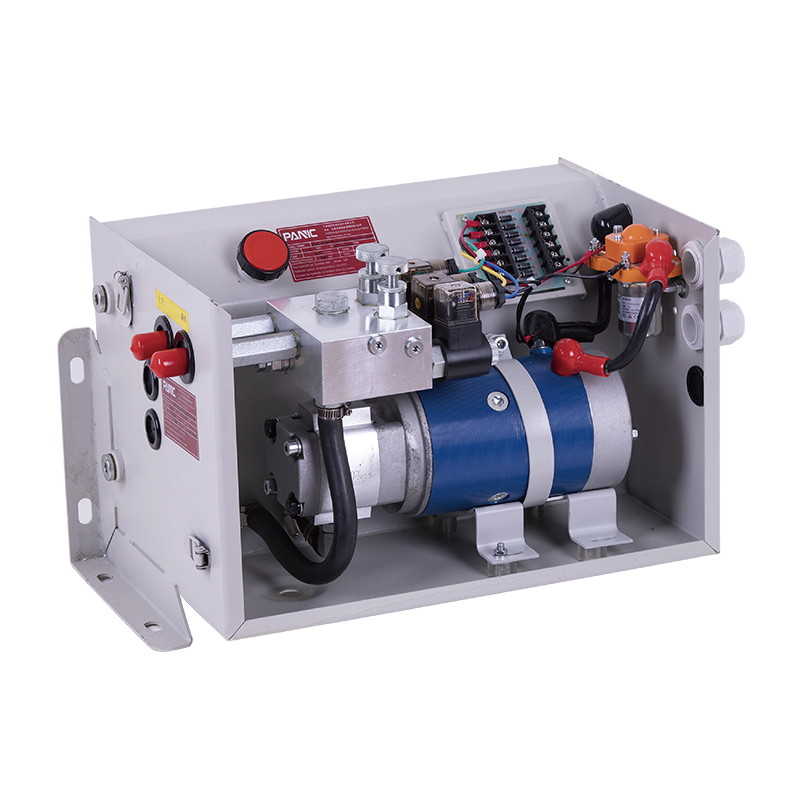
Power unit of forward moving stacker
Cat:DC series hydraulic power unit
This hydraulic power unit is specially designed for the forward stacker. It is integrated by a high-pressure gear pump, a DC Carbon brush or brushless...
See DetailsContent
A cooling distribution unit (CDU) is the piece of equipment that separates a data center's facility water loop from the technology cooling loop that touches servers directly, and it is the single component most responsible for whether a liquid cooling deployment runs reliably at rack density above 40kW. The short answer for anyone evaluating one: a CDU regulates flow, pressure, temperature and filtration between two independent liquid loops using a heat exchanger, pumps, valves and sensors, and the unit you pick should be sized around your rack heat load, your facility water temperature, and your redundancy requirements rather than around a generic catalog spec sheet.
This article walks through how a cooling distribution unit works, how it interacts with a DC hydraulic power unit in liquid-cooled racks that use pumped single-phase or two-phase cold plates, how the secondary loop fluid is chosen and maintained, how sizing and redundancy decisions are made in practice, what installation and commissioning teams get wrong most often, and what buyers ask most frequently when comparing vendors for 2025 and 2026 deployments. Given how much liquid cooling infrastructure is being installed right now to support high density accelerator racks, the goal here is to give a full working reference rather than a surface level overview.
Every liquid-cooled server rack needs two water loops that never mix. The facility loop carries water or a water-glycol mix from a chiller plant, a dry cooler, or a cooling tower to the row of racks. The technology loop, sometimes called the secondary loop, circulates a much cleaner and tightly controlled fluid directly through cold plates mounted on CPUs, GPUs and memory. The cooling distribution unit sits between these two loops and performs four jobs at once.
First, it exchanges heat from the secondary loop into the facility loop through a plate heat exchanger, without ever letting the two fluids physically touch. Second, it pumps the secondary fluid through the server manifolds at a controlled flow rate, usually measured in liters per minute per rack. Third, it filters particulates out of the secondary loop to protect the narrow channels inside cold plates, which can be as small as 0.3 millimeters. Fourth, it monitors and reports temperature, pressure, flow, and leak status back to the data center's building management system.
Because the secondary loop is sealed and small in volume compared to the facility loop, it can run at a tighter, more predictable temperature than the raw building water, which is why cold plate cooling can support chip thermal design power figures that air cooling cannot reach. A rack that would need several thousand cubic feet per minute of airflow to stay within safe operating temperature can instead be cooled with a few tens of liters per minute of circulating fluid, which is a large part of why liquid cooling is now considered the practical ceiling breaker for accelerator density.
It is worth being precise about what the CDU is not. It is not a chiller, it does not generate cold temperatures from nothing, and it does not replace the mechanical plant. It is a transfer and control device sitting between the plant and the rack, and its job is to make sure the fluid touching the chips stays within a narrow, stable band regardless of what the facility loop is doing on the other side of the heat exchanger.
Cooling distribution units did not start in commercial data centers. The core design, a sealed secondary loop isolated from a facility water supply through a plate heat exchanger, originated in high performance computing labs and industrial process cooling applications decades earlier, where sensitive equipment needed clean, chemically controlled water rather than whatever came out of a building's chilled water riser. Supercomputing centers adopted this approach early because their processors ran hotter and denser than anything in a typical enterprise server room.
As GPU-based computing moved from a research niche into mainstream cloud and enterprise infrastructure, the same isolation principle got repackaged into a product category aimed at data center operators who had never previously touched a liquid loop. What used to be a custom-engineered skid built for a single supercomputer installation became a standardized, rack-mountable or floor-standing product with defined capacity tiers, plug-and-play manifolds, and remote monitoring built in from the factory. That standardization is the main reason liquid cooling has become viable at commercial scale rather than remaining a specialty tool for national laboratories.
Cooling distribution units are generally sold in three physical formats, and the choice affects everything from floor space to cabling to redundancy planning.
| CDU Format | Typical Cooling Capacity | Racks Served | Common Placement |
|---|---|---|---|
| In-Rack CDU | 20 to 80 kW | 1 | Bottom or top of a single cabinet |
| In-Row CDU | 100 to 400 kW | 4 to 10 | Dedicated slot within the row |
| Sidecar or Room-Level CDU | 500 kW to 2 MW plus | One full pod or hall | Adjacent mechanical room or end of row |
In-rack units are attractive for retrofits because they require the smallest secondary loop footprint and can be added to a single cabinet without touching the rest of the row, but they multiply the number of pumps, filters, and heat exchangers that need periodic servicing across a hall. In-row units strike a middle ground that many colocation providers favor because a single unit failure only affects a handful of cabinets rather than an entire pod, and the unit can usually be pulled and serviced from the front without disturbing neighboring racks.
Sidecar and room-level units are becoming the more common choice for new AI training clusters because centralizing pumping and heat exchange reduces the number of moving parts per rack and simplifies leak detection zones, even though it requires a larger secondary loop piping run and more careful pressure balancing across a longer distribution network. Operators moving to very high density training pods, often in the range of 100 kW and above per rack, tend to gravitate toward this format because it lets the mechanical design team concentrate maintenance access, spare parts, and monitoring in one place instead of spreading it across dozens of cabinet-level units.

Beyond physical format, CDUs also differ in how they reject heat. A liquid-to-liquid CDU, which is the more common configuration in new builds, exchanges heat directly with a facility chilled water or condenser water loop through a plate heat exchanger. A liquid-to-air CDU instead rejects heat to room air through a radiator and fan assembly, which means it does not require a facility water connection at all.
This architecture scales to much higher densities because water carries far more heat per unit of flow than air does, and it decouples the secondary loop entirely from room air conditions, which makes performance far more predictable. It is the standard choice for any facility that already has a chilled water plant or a dry cooler loop available at the rack row.
This architecture is useful in retrofit situations where running new chilled water piping to a row is impractical, or in smaller edge sites that have no facility water loop at all. The tradeoff is that liquid-to-air units still depend on room air temperature for their ultimate heat rejection, so their capacity and efficiency degrade somewhat in hot rooms, and they contribute additional heat back into the room that the room's air conditioning system then has to remove.
Some of the confusion buyers run into comes from mixing up hydraulic power units built for industrial machinery with the pumping packages inside a cooling distribution unit. A DC hydraulic power unit, in the cooling context, refers to a compact pump-motor-reservoir assembly that runs on direct current, most commonly 24V or 48V, and drives fluid circulation for smaller or edge-deployed liquid cooling skids where a full three-phase AC pump package would be oversized or unavailable.
DC-driven pump modules show up most often in three situations: telecom edge cabinets that only have DC power plants on site, containerized or modular data centers built for remote locations without stable three-phase supply, and redundant standby pump assemblies that need to keep circulating fluid during a momentary AC power transfer. In these cases the DC hydraulic power unit acts as the muscle inside the CDU, moving coolant through the manifold and cold plates while the CDU's control board manages valve position, bypass mixing, and temperature setpoints.
A well-designed CDU built around a DC pump architecture typically includes a small battery or supercapacitor buffer so pumping does not stop even for the few hundred milliseconds it takes an automatic transfer switch to move between utility feeds, since even a brief pump interruption can allow localized hot spots on a fully loaded GPU cold plate. Telecom operators in particular have long relied on 48V DC plants for all equipment in a cabinet, and extending that same DC bus to the cooling pump avoids the need for a separate AC feed just to run cooling hardware.
Sizing follows the same underlying physics as any pump selection: required flow rate against system pressure drop determines the motor power needed, and then the DC voltage and current draw are derived from that power figure. A small edge cooling skid supporting a single rack might only need a DC pump drawing under 150 watts, while a larger sidecar unit built around a DC bus for a full pod could require a bank of pumps and a much larger reservoir, at which point many operators evaluate whether a DC architecture still makes sense compared to standard three-phase AC pumping.
Because DC hydraulic power units are frequently deployed at unmanned or lightly staffed edge sites, redundancy and remote diagnostics matter even more than in a staffed data hall. Look for dual redundant pump heads sharing a single reservoir, current draw monitoring that can flag a failing motor bearing before it fails outright, and a controller that can report status over a standard interface even when the site has no on-site IT staff to physically inspect the unit.
Each of these components plays a distinct role in overall reliability, and skipping any one of them to reduce cost tends to show up later as a maintenance or downtime problem rather than an upfront savings. Isolation valves in particular are frequently overlooked in budget designs, and their absence turns a routine pump swap into an event that requires draining and refilling the entire secondary loop for the row.
Undersizing a CDU is the most common and most expensive mistake operators make, because a unit that looks adequate on paper at design load often cannot handle the transient power spikes that modern GPU clusters produce during training bursts. Three numbers matter most when sizing.
Add up the thermal design power of every liquid-cooled component in the row, then apply a safety margin of at least 20 percent for future rack upgrades. A unit rated at exactly today's load leaves no headroom when a customer swaps in a higher wattage accelerator generation eighteen months later, and retrofitting a CDU after the fact is far more disruptive than specifying extra margin from the start.
This is the temperature difference between the facility water entering the heat exchanger and the technology loop water leaving it. A tighter approach temperature, commonly 2 to 3 degrees Celsius on well-designed units, means the CDU can deliver cooler water to the chips even when facility water runs warm, which matters a great deal in climates or seasons where a dry cooler cannot produce very cold water. A wider approach temperature, by contrast, forces the facility plant to run colder to compensate, which increases chiller energy use across the whole building.
Most cold plate manufacturers specify a required flow rate per accelerator, often in the range of 1 to 3 liters per minute per GPU. Multiply this by the number of accelerators in a rack, then confirm the CDU's rated pump curve can maintain that flow against the pressure drop of the full manifold, tubing, and quick-disconnect fittings, since quick-disconnects alone can account for a meaningful share of total system pressure loss. It is common for teams to size pumps against the cold plate pressure drop alone and forget to add the manifold and fitting losses, which then shows up as lower than expected flow once the system is fully built out.
A cluster rarely runs at full rated power continuously. Idle periods, batch job scheduling gaps, and maintenance windows all create partial load conditions, and a CDU with variable speed pumps can throttle down during these periods to save energy rather than running at full flow regardless of actual heat load. Fixed speed pump designs waste a measurable amount of energy compared to variable speed designs once real-world utilization patterns are taken into account.

The secondary loop fluid is not simply tap water. Most operators use deionized water with a corrosion inhibitor package, or a propylene glycol mix when freeze protection is required in outdoor or edge deployments. Untreated or poorly filtered fluid is the leading cause of premature cold plate failure, because scale buildup and biological growth reduce the internal channel diameter over time and raise the thermal resistance between the chip and the coolant.
Operators typically test secondary loop fluid on a quarterly basis for pH, conductivity, and dissolved oxygen, and many CDU vendors now integrate inline conductivity sensors that flag when fluid needs replacement before it degrades cooling performance. A well-maintained loop with continuous filtration can run for three to five years between full fluid replacements, according to guidance published by cooling equipment manufacturers and confirmed in field data shared by colocation operators running dense GPU pods.
| Fluid Type | Freeze Protection | Relative Heat Transfer | Typical Application |
|---|---|---|---|
| Deionized Water | None | Highest | Indoor data halls with stable temperature |
| Propylene Glycol Mix | Moderate to high | Slightly reduced | Outdoor skids and edge sites |
| Dielectric Fluid | Varies by formulation | Lower than water | Immersion cooling tanks paired with a CDU |
A layered filtration approach works best in practice: a coarse strainer at the CDU inlet to catch large debris, a finer particulate filter rated around 25 to 50 microns positioned before the fluid reaches the manifold, and a bypass filtration loop that continuously polishes a small side stream of fluid even while the main loop is running. This layered approach catches most contamination before it ever reaches a cold plate, where the tight internal channels make even small particles a real blockage risk.
| Configuration | Description | Typical Use Case |
|---|---|---|
| N | One CDU per row with no backup unit | Development or test clusters |
| N+1 | One extra CDU shared across several rows | Standard enterprise colocation |
| 2N | Fully duplicated CDU and piping per row | Critical AI training halls with strict uptime targets |
Pump redundancy inside a single CDU chassis is a separate consideration from unit-level redundancy across a row, and most specifications now call for both dual internal pumps and at least N+1 unit sparing for any deployment supporting revenue-generating compute. The distinction matters because internal pump redundancy protects against a single pump failure while the CDU itself keeps running, whereas unit-level redundancy protects against a failure of the entire CDU, including its heat exchanger, controller, or valve train.
A 2N architecture, where every row has a fully duplicated CDU and an independent piping path, is the most resilient but also roughly doubles capital cost for the cooling distribution layer, so it tends to be reserved for facilities where even a brief cooling interruption would cause an unacceptable loss of a long-running training job or production workload.
A modern CDU is as much a data source as it is a mechanical device. Every unit worth deploying today reports flow rate, supply and return temperature on both loops, differential pressure, pump speed and current draw, filter condition, and leak status back to a central monitoring platform. This telemetry feeds into the facility's data center infrastructure management software, where operators can correlate cooling performance directly against IT load.
Beyond simple high and low temperature alarms, well-run facilities configure rate-of-change alarms that catch a slow drift toward a problem well before an absolute threshold is crossed. A flow rate that gradually declines over several weeks, for example, often signals a filter approaching capacity long before it triggers a hard low-flow alarm, and catching that trend early avoids an unplanned filter change during a high load period.
Facilities that tie CDU telemetry directly to server power draw data can build predictive models that anticipate cooling demand ahead of a scheduled workload, rather than only reacting after temperatures rise. This is particularly valuable for AI training clusters, where power draw can swing dramatically within seconds as a job moves between compute-heavy and communication-heavy phases, and a CDU control loop that can anticipate these swings performs measurably better than one that only reacts to temperature after the fact.
Because liquid cooling moves heat more efficiently than air, facilities that shift meaningful IT load onto CDU-served racks generally see a measurable improvement in overall facility power usage effectiveness, since the mechanical plant spends less energy moving air and more of the total power draw goes directly toward computing. Variable speed pumps inside the CDU further reduce parasitic energy use by only pumping as much flow as the current heat load actually requires rather than running fixed speed regardless of load.
Facilities that pair CDUs with a dry cooler or free cooling loop can also extend the number of hours per year during which no mechanical chiller is needed at all, since the CDU's tight approach temperature control allows useful cooling even from moderately warm facility water. Operators in cooler climates have reported extending free cooling hours meaningfully by combining a low-approach-temperature CDU with a well-tuned dry cooler control strategy, according to case studies published by cooling equipment manufacturers and academic data center efficiency researchers.
| Task | Recommended Frequency |
|---|---|
| Fluid quality test (pH, conductivity, dissolved oxygen) | Quarterly |
| Particulate filter inspection or replacement | Every 3 to 6 months |
| Pump bearing and seal inspection | Annually |
| Heat exchanger fouling check | Annually |
| Leak sensor functional test | Semi-annually |
| Full pump rebuild or replacement | Every 5 to 7 years or per run-hour threshold |
A gradual decline in flow rate almost always points to a filter approaching capacity or early scale buildup somewhere in the loop. Checking differential pressure across the filter housing is usually the fastest way to confirm the cause before scheduling a filter change.
If the gap between facility supply temperature and technology loop supply temperature grows wider than the unit's rated approach, the heat exchanger plates are likely fouling on either the facility or technology side, or facility flow to the unit has dropped due to a partially closed valve elsewhere in the row.
Nuisance leak alarms are often caused by condensation forming on cold supply lines in a humid room rather than an actual fluid leak. Insulating exposed cold piping and confirming room humidity control usually resolves this without needing to open the loop at all.
Pumps that cycle on and off rapidly rather than running steadily at a controlled speed usually indicate an undersized expansion tank or an air pocket trapped in the loop that is causing pressure to swing beyond the controller's setpoint band.

Immersion cooling tanks, where entire servers sit submerged in a dielectric fluid, still need a way to reject the heat that fluid absorbs, and a cooling distribution unit is commonly used for exactly this purpose. In this configuration the CDU's secondary loop circulates dielectric fluid through a heat exchanger connected to the tank rather than through cold plates, while the primary loop still connects out to the facility water supply in the same way it would for a cold plate deployment.
The main design difference is that dielectric fluids generally have lower thermal conductivity and higher viscosity than water, so pumps and heat exchangers sized for a water-based cold plate loop are not automatically appropriate for an immersion loop, and vendors typically offer separate CDU model lines tuned specifically for dielectric fluid properties.
The sticker price of a cooling distribution unit is only one part of total deployment cost. Piping, manifolds, quick-disconnect fittings, insulation, leak containment trays, and commissioning labor frequently add up to a similar or larger share of total spend, particularly in retrofit projects where existing raised floor or overhead pathways were not designed with liquid piping in mind. Ongoing costs include fluid replacement, filter consumables, and the electricity the pumps themselves draw, which is a small fraction of total facility power but still worth including in long-term operating budgets.
Facilities planning multi-phase buildouts often find it more economical to install a larger sidecar CDU with headroom for future phases than to install several smaller units sequentially, since piping and commissioning labor scale more with the number of separate installation events than with the physical size of a single unit.
Liquid cooling adoption has moved quickly from a niche high-performance computing tool to a mainstream requirement for AI training and inference infrastructure, driven directly by accelerator thermal design power figures that now regularly exceed 700 to 1000 watts per chip. This shift has pushed cooling distribution unit vendors toward larger sidecar and room-level units, tighter approach temperatures, and pump architectures, including DC-driven modules, that can integrate more easily with on-site battery and power infrastructure for continuous operation during power transitions.
Facilities that standardized on air cooling as recently as three years ago are now retrofitting mechanical rooms specifically to host row after row of CDUs, and floor space once reserved for computer room air handlers is increasingly allocated to liquid cooling infrastructure instead. Vendors are also converging on more standardized manifold and quick-disconnect interfaces, which reduces the custom engineering burden every time a new server generation is introduced and makes it easier for operators to mix hardware from multiple manufacturers within the same liquid-cooled row.
A chiller produces cold water for an entire building or data hall by removing heat and rejecting it outdoors. A cooling distribution unit does not produce cooling on its own; it transfers heat from the rack-level technology loop into the facility water that the chiller has already cooled, while keeping the two loops physically separate.
Yes, some CDUs pair with a dry cooler or free cooling loop instead of a mechanical chiller, particularly in cooler climates where outdoor air temperature is low enough for most of the year to reject heat without compressor-based cooling. Liquid-to-air CDUs also exist that do not require any facility water connection at all.
Most manufacturers recommend an annual inspection of pump seals, bearings, and motor current draw, with a full pump rebuild or replacement typically scheduled between five and seven years depending on run hours and fluid quality.
This varies by cold plate design, but a common range is 15 to 40 liters per minute for a fully populated eight-accelerator server, meaning a rack with several such servers can require well over 100 liters per minute of total flow from the CDU.
DC-driven pump modules are chosen when the facility's available power infrastructure is already DC-based, such as telecom sites, or when the deployment needs uninterrupted pumping through short AC power transitions using a local battery buffer rather than relying on generator start time.
In a properly designed N+1 pump configuration inside the CDU, a backup pump automatically takes over flow duty within seconds, and the building management system raises an alarm so maintenance staff can replace the failed pump without an outage.
Leak risk is managed through dry-break quick-disconnect fittings at every hose connection, cable-based leak sensors placed under manifolds and at the base of the enclosure, and secondary containment trays that catch any fluid before it reaches server electronics or the raised floor.
Yes, as long as the manifold and quick-disconnect interfaces are compatible or adapted with the correct fittings, a single CDU can serve mixed hardware within its rated flow and capacity limits, which is increasingly common as facilities standardize on common secondary loop interfaces.
With continuous filtration and periodic quality testing, secondary loop fluid commonly lasts three to five years before a full replacement is needed, though conductivity and pH testing results should guide the actual replacement schedule rather than a fixed calendar date alone.
Field experience across multiple operators consistently points to fluid contamination and filter neglect as the leading cause of performance degradation, followed by undersized expansion tanks that cause pressure related shutdowns during periods of high thermal load.

This hydraulic power unit is specially designed for the forward stacker. It is integrated by a high-pressure gear pump, a DC Carbon brush or brushless...
See Details
This hydraulic power unit is specially designed for the hydraulic tail plate. The vehicle tail plate hydraulic power unit is a power unit used for the...
See Details
This hydraulic pump station is composed of a series of side inlet and side outlet gear pumps and 4.5 or 5-inch DC motors. It is often used as a hydrau...
See Details
This hydraulic pump station is specially designed for a self-propelled aerial work vehicle. It is composed of 2 series side inlet and side outlet gear...
See Details
This DC double acting power unit is an integrated hydraulic system designed for various equipment that requires efficient hydraulic drive. It is suita...
See Details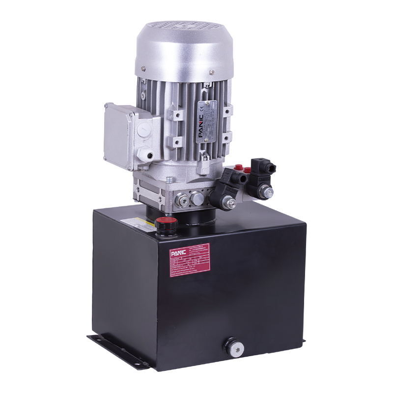
This hydraulic power unit is designed for scissor lifts and integrates a high-pressure gear pump, AC motor, center valve block, cartridge valve and oi...
See Details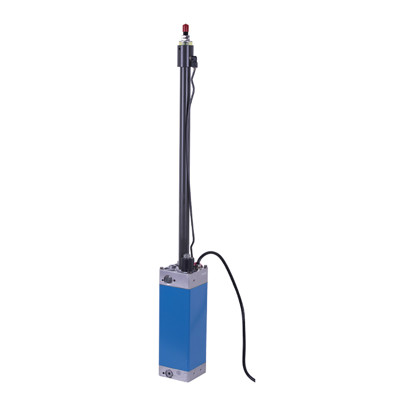
The hydraulic power unit is specially designed for the integrated hydraulic lifting column, which is integrated by a two-way gear pump, an AC Oil imme...
See Details
This oil immersed double actina power unit is designed for efficient, compact and low noise applications, integrating high pressure gear pump, AC oil ...
See Details
ET series hydraulic lifting platform valve group is specially designed for various hydraulic lifting platforms. It can accurately control the lifting ...
See Details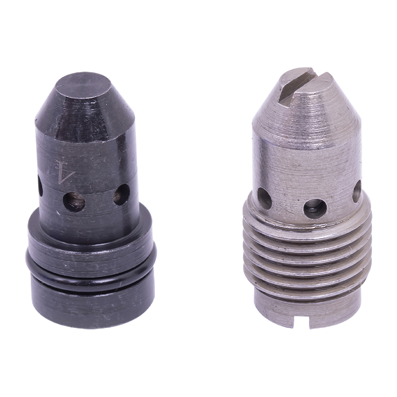
The pressure compensation valve is a key component in the hydraulic system to maintain flow stability. It can automatically adjust the valve opening w...
See Details
No. 12 Tongji Road, Simen Town, Yuyao City

+86-0574-62130352
+86-18905846028

+86-0574-62130353

Copyright© Ningbo Panic Hydraulic Technology Co., Ltd. All Rights Reserved. China Hydraulic Power Units Manufacturers

