


 English
 中文简体
中文简体 русский
Mini Pallet Truck Hydraulic Power Unit
Cat:DC series hydraulic power unit
This hydraulic power unit is specially designed for all electric pallet truck.It consists of high voltage gear pump,permanent magnet DC motor and cent...
See DetailsContent
A hydraulic power unit is built from six functional groups working together: a reservoir that stores and conditions the fluid, a pump that converts mechanical energy into flow, an electric motor that drives the pump, a valve assembly that directs and regulates pressure, a filtration circuit that protects internal surfaces from contamination, and supporting hardware such as coolers, accumulators, manifolds, seals, and instrumentation. Every one of these hydraulic power unit components has a direct effect on system pressure stability, fluid life, and how long the unit runs before it needs service.
The sizing and grade of each part depend on duty cycle, ambient temperature, and the pressure the downstream actuators demand. A unit built for a stamping press that fires every few seconds needs different valve response and cooling capacity than a unit that holds a static clamp for hours. Matching components to the actual duty cycle, rather than defaulting to a catalog-standard configuration, is usually the difference between a power unit that lasts a decade and one that needs a rebuild in two years.
It also helps to think of a hydraulic power unit as a closed loop rather than a collection of separate parts. Fluid quality set by the reservoir and filtration circuit affects pump wear, pump wear affects internal leakage and heat generation, heat affects viscosity, and viscosity affects how precisely the valves can control flow. A weak link in any single component group eventually shows up as a symptom somewhere else in the circuit, which is why troubleshooting a power unit almost always has to start with fluid condition before looking at any individual part.
The sections below walk through each major component group, what changes between configurations, the standards and data points engineers commonly reference when specifying parts, and the failure patterns that show up most often in the field.
The reservoir does more than hold oil. It settles entrained air, dissipates heat through its surface area, and allows contaminants to drop out before fluid is drawn back into the pump inlet. A reservoir that is undersized for its pump flow rate will re-circulate hot, aerated fluid, which accelerates oxidation and shortens seal life across every other component in the circuit.
A widely used starting rule sizes the reservoir at three to five times the pump's rated flow in gallons per minute, expressed in gallons. A unit built around a 20 GPM pump would therefore typically use a 60 to 100 gallon tank, with the lower end reserved for units that already include auxiliary cooling.
| Duty Type | Recommended Tank-to-Flow Ratio | Typical Baffle Configuration |
|---|---|---|
| Continuous run, high heat load | 4:1 to 5:1 | Full-height baffle plate with return diffuser |
| Intermittent duty, standard press work | 3:1 to 4:1 | Partial baffle separating suction and return |
| Mobile or space-constrained units | 2:1 to 3:1 | Internal diffuser only, no full baffle |
Reservoirs also carry the fill and drain ports, a breather with a desiccant or particulate element, a magnetic drain plug to catch ferrous wear debris, and a sight glass or float-style level gauge. Skipping the magnetic plug is a common shortcut on lower-cost hydraulic power unit builds, and it is one of the cheapest additions relative to the wear protection it provides.
The internal baffle plate is often overlooked, but its placement determines how much dwell time fluid has before it is drawn back into the pump. A baffle set too close to the suction port shortens the effective settling distance and lets aerated fluid recirculate faster than it can de-gas. Return lines are typically cut at a 45-degree angle and positioned below the fluid surface to reduce splashing and foam formation, and a diffuser fitting on the return line spreads flow across a wider area rather than directing a high-velocity stream straight at the tank wall.
Carbon steel remains the standard reservoir material for cost reasons, usually finished with an interior coating resistant to the specific fluid type in use, since mineral oil, water-glycol, and biodegradable fluids each interact differently with untreated steel. Stainless steel reservoirs appear on units in food-grade, washdown, or corrosive environments where coating failure would introduce contamination risk. Aluminum tanks show up on mobile and weight-sensitive builds, trading some dent resistance for a meaningful weight reduction.
The fluid itself is a working component, not just a medium, and choosing the wrong grade undermines every other part in the circuit regardless of how well those parts are specified.
Viscosity is generally specified by ISO grade, with ISO 32 and ISO 46 covering most moderate-climate industrial applications and ISO 68 reserved for units running in consistently high ambient temperatures. Running a fluid that is too thin for the operating temperature increases internal leakage across the pump and valves, lowering volumetric efficiency, while fluid that is too thick raises pump inlet restriction and can starve the pump at startup in cold conditions. A viscosity index above 100 indicates the fluid resists thinning as temperature rises, which matters more on units that see a wide seasonal temperature swing than on climate-controlled indoor installations.
The pump sets the flow rate and, combined with the relief valve setting, the maximum working pressure of the entire unit. Three pump architectures cover the large majority of industrial hydraulic power unit builds.
A fixed displacement pump delivers a constant flow rate at a given shaft speed regardless of load, with excess flow bypassed across the relief valve as heat. A variable displacement, pressure-compensated pump reduces its own output once the system reaches set pressure, which cuts heat generation and electrical draw substantially on units with long dwell periods. The higher upfront cost of a variable pump is frequently recovered within a few years through lower cooling and energy costs on units that spend most of their cycle holding pressure rather than moving flow.
Most industrial pumps mount directly to the motor through a bell housing and flexible coupling rather than a belt drive, which keeps shaft alignment consistent and avoids the maintenance overhead of belt tensioning. Coupling material selection matters more than it might appear — a coupling that is too stiff transmits motor vibration directly into the pump shaft and accelerates bearing wear, while a coupling that is too soft can wind up under sudden load reversals. Alignment tolerance between motor and pump shaft is typically held within a few thousandths of an inch, since misalignment beyond that range shows up as premature shaft seal leakage long before it affects performance.
A new piston pump typically operates at 92 to 97 percent volumetric efficiency, meaning only a small percentage of theoretical output is lost to internal slippage. As the pump wears, that slippage increases, and pressure holds less steadily under load even though the pump may still start and run normally. Tracking output flow or pressure decay under a fixed load over time gives a much earlier warning of pump wear than waiting for a complete failure.
The motor has to match the pump's horsepower requirement at the intended operating pressure, not just its flow rating. Horsepower for a hydraulic circuit is calculated from flow and pressure together, so a pump that looks modest on flow alone can still demand a large motor if it is expected to hold high pressure continuously.
| Motor Frame | Common Horsepower Range | Typical Application |
|---|---|---|
| NEMA 56C / 143TC-145TC | 1 to 5 HP | Small mobile units, single-actuator lifts |
| 184TC-215TC | 7.5 to 20 HP | Standard industrial presses and clamps |
| 254TC and larger | 25 HP and above | Continuous-duty industrial machinery, injection molding |
TEFC (totally enclosed, fan-cooled) motors dominate industrial hydraulic power unit installations because the pump end is exposed to oil mist and airborne particulate. Duty cycle also matters here: a motor rated for continuous duty (S1) will run cooler over an eight-hour shift than a motor rated only for intermittent duty, even if both share the same nameplate horsepower.
Direct-on-line starting is common for smaller motors but produces an inrush current several times the rated running current, which can be a problem on facilities with limited electrical service or on units that start and stop frequently throughout a shift. Soft starters and variable frequency drives reduce that inrush, and a variable frequency drive additionally allows the motor speed to be reduced during low-demand periods of the cycle, which cuts both energy use and noise. On units where the pump is fixed displacement, pairing it with a VFD is one of the more effective retrofit changes for reducing standby energy consumption without replacing the pump itself.
Motor nameplate ratings assume a standard ambient temperature, commonly 40°C. Units installed in enclosed cabinets, hot mechanical rooms, or direct sunlight often run at a higher ambient than that baseline, and the motor's usable horsepower has to be derated accordingly or the motor will run hotter than its insulation class is rated for, shortening winding life well before any mechanical failure occurs.
Valves are where a hydraulic power unit's behavior is actually shaped. Three valve families appear in nearly every build, alongside several specialty valve types used in more demanding circuits.
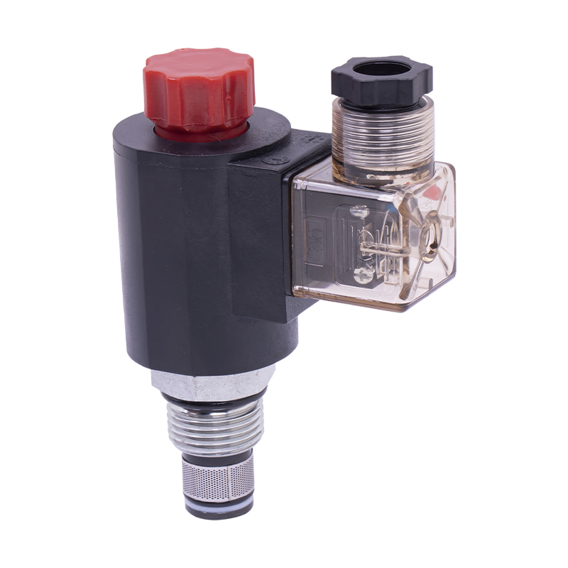
Solenoid-operated directional valves route flow to extend, retract, or hold an actuator. Spool configuration determines whether the circuit is open-center, closed-center, or tandem-center at rest, which in turn affects how the pump behaves when the valve is not shifted. Response time on a standard wet-armature solenoid valve is typically in the range of 20 to 50 milliseconds, while proportional directional valves trade some of that speed for a controlled, ramped transition that reduces shock loading on the actuator and connected structure.
The relief valve sets the absolute pressure ceiling of the circuit and protects every downstream component from an overload event. It is typically set 10 to 20 percent above the highest working pressure the system needs, giving margin without wasting energy across the relief path during normal operation. Pilot-operated relief valves hold a tighter pressure tolerance under varying flow than direct-acting relief valves and are the standard choice on any circuit above roughly 10 GPM.
Needle valves, pressure-compensated flow controls, and flow dividers manage actuator speed independent of load variation. Pressure-compensated versions hold a set flow rate even as load pressure changes, which matters on any application where cycle time consistency is required, such as synchronized clamping.
On vertical actuators, a counterbalance valve prevents an overrunning load from free-falling if a hose ruptures or a directional valve loses signal, by maintaining back-pressure on the actuator's outlet side until the inlet side is actively pressurized. Load-holding valves of this type are treated as safety-critical components on any application where an uncontrolled descent would create a hazard, such as lift platforms or press rams.
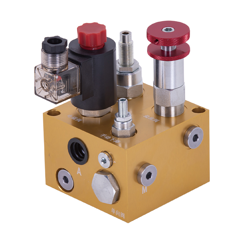
Valve manifolds increasingly combine several of these functions into a single cast or drilled block, cutting the number of external fittings and leak points compared to a stack of separately piped valves.
Contamination is responsible for the majority of unplanned hydraulic component failures, and filtration is the primary defense. A well-specified hydraulic power unit uses filtration at more than one point in the circuit rather than relying on a single filter location.
| Filter Location | Typical Micron Rating | Primary Purpose |
|---|---|---|
| Suction strainer | 100 to 150 micron | Protects pump inlet from large debris |
| Pressure line filter | 10 to 25 micron | Protects valves and cylinders downstream of the pump |
| Return line filter | 10 to 25 micron | Catches wear debris before it re-enters the reservoir |
Fluid cleanliness is commonly tracked using ISO 4406 particle counting, which reports three numbers representing particle counts at 4, 6, and 14 microns. A code such as 18/16/13 is a realistic target for a mid-pressure industrial circuit, while proportional and servo valves generally call for a tighter code in the range of 16/14/11. A clogging indicator, whether visual or electrical, lets maintenance staff change elements based on actual condition instead of a fixed calendar interval, which reduces both premature element changes and the risk of running past a filter's capacity.
Filter element performance is often expressed as a beta ratio, which compares the number of particles above a given size upstream and downstream of the element. A beta ratio of 200 at 10 microns means the filter removes 199 out of every 200 particles of that size or larger, and is considered a high-efficiency rating for a pressure line filter. Beta ratio matters more than headline micron rating alone, since two filters advertised at the same micron size can have very different actual capture efficiency depending on media construction.
Some hydraulic power units add a dedicated off-line filtration loop, running continuously off a small auxiliary pump independent of the main circuit's duty cycle. This kidney-loop arrangement keeps the reservoir clean even during periods when the main pump is idle, and is common on large-volume reservoirs where in-line filtration alone cannot turn over the full fluid volume often enough to hold a tight cleanliness target.
An accumulator stores hydraulic energy under pressure, using a piston, bladder, or diaphragm to separate the fluid from a pre-charged gas volume, almost always nitrogen. In a hydraulic power unit, accumulators serve several distinct purposes.
Bladder-style accumulators are the most common choice in general industrial service because they offer a good balance of response speed and cost. Pre-charge pressure is normally set to roughly 90 percent of the minimum system operating pressure and needs to be checked periodically, since nitrogen charge does drop slowly over time through the bladder material.
Piston accumulators use a free-floating piston instead of a flexible bladder to separate gas and fluid, which allows them to handle larger volumes and higher cycle rates without the fatigue concerns that limit bladder life under constant rapid cycling. They are more common on continuous-duty industrial presses and test equipment where the accumulator sees thousands of charge and discharge cycles per shift.
Every inefficiency in a hydraulic circuit shows up as heat, and excess heat is one of the fastest ways to degrade both the fluid and the seals throughout the unit. Air-cooled heat exchangers use a fan-driven radiator core and suit installations where ambient air is available and water is not, while water-cooled shell-and-tube exchangers offer more consistent cooling in hot or dusty environments but require a chilled or once-through water supply.
Cooling capacity is generally matched to the heat load generated by relief valve bypass, pressure drop across valves, and pump inefficiency, not simply to motor horsepower. Units running a fixed-displacement pump against a closed-center valve for long dwell periods generate significantly more heat than a variable-displacement pump doing the same job, and the cooler specification should reflect that difference rather than a generic horsepower-based rule of thumb.
A thermostatically controlled fan or a bypass valve on the water-cooled circuit keeps fluid temperature from swinging too far in either direction, since fluid that runs too cool increases viscosity and pump inlet restriction just as running too hot lowers viscosity and film strength.
Air-cooled units avoid the plumbing, water treatment, and discharge permitting concerns that come with a water-cooled system, which makes them the simpler choice for most standalone industrial installations. Water-cooled units, in exchange, hold a more stable fluid temperature regardless of ambient air conditions and take up less physical space around the unit itself, which matters in facilities where floor space or airflow clearance is limited. Some larger installations use a closed-loop water-to-air chiller specifically to get the stability of water cooling without the water consumption and discharge concerns of an open once-through system.
Manifold blocks consolidate valve mounting and internal porting into a single machined or cast body, cutting down the number of external hose runs and the leak points that come with them. Cartridge-style valves threaded directly into manifold cavities have largely replaced older stacked-valve assemblies on new hydraulic power unit builds because they reduce both footprint and assembly labor.
Hose is rated by working pressure, burst pressure, and bend radius, and undersized hose is one of the more common causes of pressure drop that gets misdiagnosed as a pump or valve problem. O-ring face seal and O-ring boss fittings are now preferred over older flare fittings on higher-pressure circuits because they seal reliably without relying on metal-to-metal torque alone, reducing weep leaks at connection points over the life of the unit.
Fixed steel or stainless piping is generally used for permanent runs between the reservoir, pump, and manifold on stationary units, since rigid piping resists abrasion and outlasts hose over the life of the installation. Flexible hose is reserved for connections to moving components, such as a cylinder that travels, or for sections that require vibration isolation from the pump and motor. Mixing the two appropriately, rather than running hose for an entire fixed circuit out of convenience during assembly, meaningfully extends the service interval between leak repairs.
Line sizing is generally set to keep fluid velocity within accepted ranges — roughly 2 to 4 feet per second on suction lines, 10 to 15 feet per second on pressure lines, and 10 to 15 feet per second on return lines. Undersized lines increase velocity beyond these ranges, which raises pressure drop, generates additional heat, and in suction lines specifically increases the risk of cavitation at the pump inlet.

Seals rarely get the same attention as pumps or valves when a hydraulic power unit is specified, but seal failure is one of the more frequent reasons a unit ends up in an unplanned repair.
The rotary shaft seal at the pump's drive shaft is exposed to constant rotation and any misalignment in the motor coupling, making it one of the highest-wear seal locations on the entire unit. Shaft seal material has to be matched to the fluid type in use, since a seal compound suited to mineral oil can degrade rapidly in contact with certain fire-resistant or biodegradable fluids.
Manifold and valve mounting surfaces rely on static O-rings or gaskets rather than dynamic seals, and these generally have a longer service life since they are not subject to continuous motion. Their failure is more often tied to incorrect bolt torque during assembly or reuse of a seal that should have been replaced during a valve swap, rather than to fluid compatibility issues.
| Fluid Type | Commonly Compatible Seal Material | Note |
|---|---|---|
| Mineral oil | Nitrile (Buna-N) | Standard default for most industrial circuits |
| Fire-resistant water-glycol | EPDM | Nitrile degrades in water-glycol fluid over time |
| Phosphate ester | Fluorocarbon (Viton) | EPDM and nitrile are both unsuitable |
Instrumentation turns a hydraulic power unit from a sealed box into something that can be diagnosed without disassembly. A minimum instrumentation package on most industrial units includes a pressure gauge with an isolator valve to protect the gauge from pulsation, a fluid level and temperature gauge on the reservoir, and a clogging indicator on the filter housings.
| Instrument | What It Monitors | Why It Matters |
|---|---|---|
| Pressure transducer | System pressure, electrically read | Enables PLC monitoring and pressure-based interlocks |
| Temperature switch | Reservoir fluid temperature | Triggers cooling or shutdown before viscosity breakdown |
| Level switch | Reservoir fluid level | Prevents pump cavitation from low fluid |
| Filter clogging indicator | Pressure differential across filter element | Flags element replacement based on actual condition |
Adding electrical outputs to these instruments, rather than relying on visual-only gauges, allows a PLC or control panel to shut the unit down automatically before a low-level or over-temperature condition causes damage, which is far cheaper than the repair that follows an ignored warning.
On larger installations, instrumentation increasingly feeds a data historian or remote monitoring platform rather than a local panel alone, letting maintenance staff track pressure and temperature trends over weeks or months instead of reacting only to an alarm. Gradual drift in these trends — a slowly rising baseline temperature, or a relief valve that bypasses more often than it used to — is frequently the earliest available warning of developing pump or cooler wear, well before the unit trips an alarm or fails outright.
Standalone hydraulic power units with simple on/off or manual valve control still make up a large share of installations, but integration with a PLC or dedicated hydraulic controller has become standard on any application where cycle timing, sequencing, or safety interlocks matter.
A discrete control scheme switches solenoid valves fully on or off, which is sufficient for simple extend-retract-hold sequences. Proportional and servo control instead modulate valve position continuously, allowing controlled acceleration, deceleration, and mid-stroke positioning. Proportional control adds cost and requires tighter fluid cleanliness, but it is what allows a hydraulic power unit to match the smooth, position-accurate motion that pneumatic or electromechanical actuators are sometimes assumed to handle better.
Pressure switches, guard interlocks, and emergency stop circuits are commonly wired directly into the motor starter and directional valve control circuit so that a safety event removes both electrical drive and hydraulic pressure at the same time, rather than relying on a software-only response that could be delayed by a control system fault.
Energy cost over the life of a hydraulic power unit frequently exceeds the original purchase price of the equipment, which makes efficiency a component-selection factor in its own right rather than a secondary concern.
These choices interact with each other: a variable displacement pump paired with a VFD-driven motor and a load-sensing manifold can cut electrical consumption substantially compared with a fixed-displacement, fixed-speed baseline on the same application, though the actual savings depend heavily on how much of the duty cycle is spent at partial demand versus full-flow operation.
The component groups covered above apply to both mobile and stationary hydraulic power units, but the specific hardware chosen within each group often differs meaningfully between the two.
| Component | Stationary Industrial Unit | Mobile Unit |
|---|---|---|
| Power source | Fixed electric motor | PTO, engine-mounted pump, or battery-electric motor |
| Reservoir material | Carbon or stainless steel | Aluminum for weight reduction |
| Cooling | Air or water heat exchanger | Ram-air or fan-assisted air cooling |
| Enclosure | Open frame or sound-dampened cabinet | Sealed, vibration-isolated compartment |
Vibration is the biggest additional design factor on mobile units. Components that would sit undisturbed for years on a stationary industrial floor need lock washers, thread-locking compound, and vibration-rated hose clamps on a mobile chassis, since sustained road or off-road vibration will loosen standard fasteners and fittings far faster than a stationary installation ever would.
Most hydraulic power unit failures trace back to one of three root causes: contamination, aeration, or heat. Recognizing the early symptoms of each lets maintenance staff intervene before a component actually fails.
| Symptom | Likely Component Affected | Common Root Cause |
|---|---|---|
| Whining or cavitation noise at the pump | Pump, suction strainer | Low fluid level, clogged strainer, or air leak on suction side |
| Spongy or delayed cylinder response | Directional or flow control valve | Aerated fluid or worn valve spool |
| Gradual pressure drop under load | Pump, relief valve | Internal wear from contaminated fluid |
| Rising fluid temperature over the shift | Cooler, relief valve | Undersized cooling or excessive relief bypass |
| Weeping fittings and hose ends | Fittings, hose assemblies | Vibration fatigue or incorrect torque at installation |
| Erratic pressure gauge or transducer reading | Gauge isolator, transducer wiring | Pulsation damage or a loose electrical connection |
A preventive schedule built around fluid sampling, scheduled filter changes based on clogging indicators rather than fixed intervals, and periodic accumulator pre-charge checks catches the large majority of these failure patterns while they are still inexpensive to correct.
Quarterly fluid sampling is a common baseline for units in continuous industrial service, with sampling moved to a monthly interval on units running high-precision proportional or servo circuits where a small increase in particle count has an outsized effect on valve response. Sampling from a live, running line rather than the reservoir bottom gives a more representative picture of what is actually circulating through the pump and valves.

Standard catalog units cover a large share of applications, but custom builds are common where footprint, noise, duty cycle, or environmental exposure fall outside standard ranges. A few practical questions shape most custom specifications.
Getting these answers right before component selection avoids the most expensive kind of rework: discovering after installation that the pump, motor, or cooling package was undersized for real operating conditions.
Where a hydraulic power unit sits near an operator station or in a noise-sensitive facility, a sound-dampened enclosure around the pump and motor can meaningfully cut perceived noise, often more cost-effectively than switching pump types alone. Enclosure design has to balance acoustic dampening against adequate ventilation, since a sealed enclosure that traps heat around the motor and pump will shorten component life even as it quiets the unit.
With proper filtration and fluid maintenance, the structural components of a hydraulic power unit commonly run 15 to 20 years, though pumps, seals, and hoses are wear items that get rebuilt or replaced on shorter cycles well before that.
Change intervals depend on operating temperature and contamination control rather than a fixed number of hours. Many industrial units run on annual or biennial fluid changes when filtration keeps particle counts low and temperature stays under control, but fluid sampling is a more reliable guide than a calendar date alone.
In most cases this requires replacing the pump and often the mounting adapter, since the two pump types differ mechanically rather than just in control logic. It is generally more practical to specify the correct pump type up front based on duty cycle than to plan on a later upgrade.
A cooler that is correctly sized on paper will still underperform if the fan or water flow is restricted, if the relief valve is bypassing more flow than intended due to a valve or pressure setting issue, or if the fluid viscosity grade does not match the operating temperature range.
Bladder accumulators respond faster and cost less for general shock absorption and pressure smoothing, while piston accumulators handle larger volumes and higher cycle rates more durably, making them a better fit for applications with frequent, large-volume demand spikes.
A suction strainer protects the pump inlet from large debris and is intentionally coarse, typically 100 to 150 micron, to avoid restricting pump inlet flow. A pressure line filter is much finer, typically 10 to 25 micron, and protects the more sensitive valves and cylinders downstream of the pump.
Pressure that holds steady with no load but drops once an actuator is engaged usually points to internal pump wear or a relief valve that is opening earlier than its set point, both of which reduce the effective flow available once the system is actually working rather than idling.
Thicker fluid resists flowing through the small internal passages inside a directional or proportional valve, slowing spool movement and actuator response. This is why cold-start delay is common on units left idle overnight in unheated spaces, and why some installations add a tank heater or a warm-up cycle before running at full speed in cold conditions.
A pilot-operated check valve allows free flow in one direction while blocking reverse flow until a pilot pressure signal deliberately opens it, which is commonly used to hold a cylinder in position without drift even when the directional valve is centered and no active pressure is being applied.
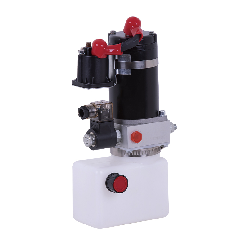
This hydraulic power unit is specially designed for all electric pallet truck.It consists of high voltage gear pump,permanent magnet DC motor and cent...
See Details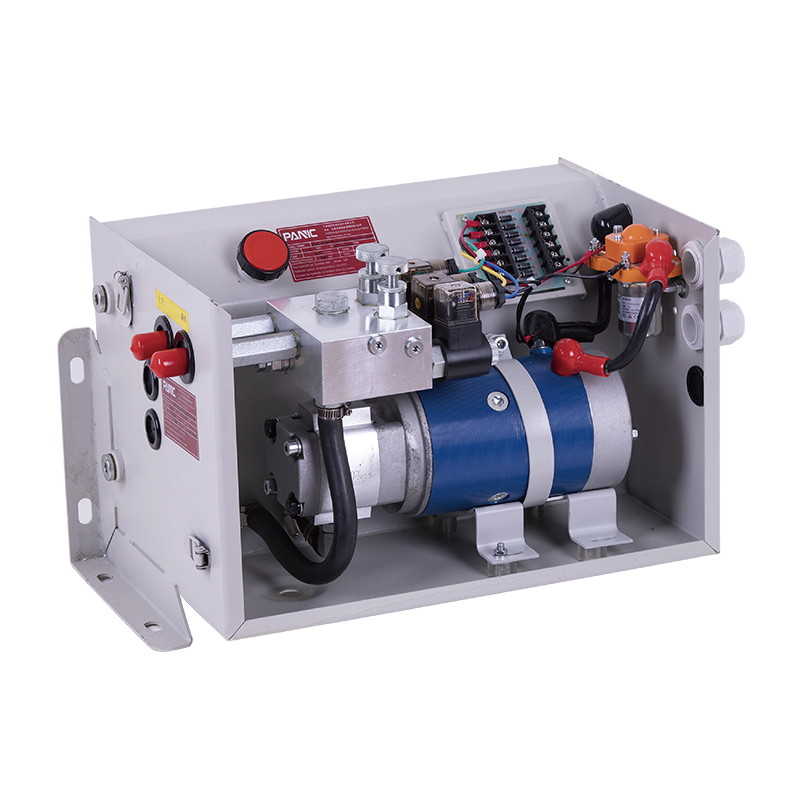
This hydraulic power unit is specially designed for the hydraulic tail plate. The vehicle tail plate hydraulic power unit is a power unit used for the...
See Details
This hydraulic pump station is specially designed for a self-propelled aerial work vehicle. It is composed of 2 series side inlet and side outlet gear...
See Details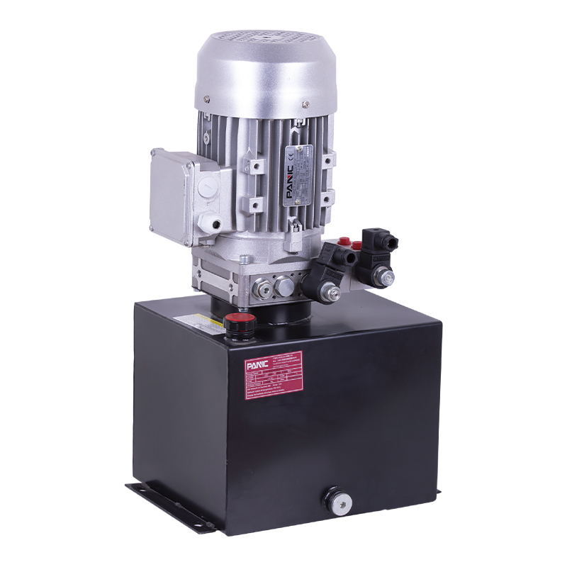
This hydraulic power unit is designed for scissor lifts and integrates a high-pressure gear pump, AC motor, center valve block, cartridge valve and oi...
See Details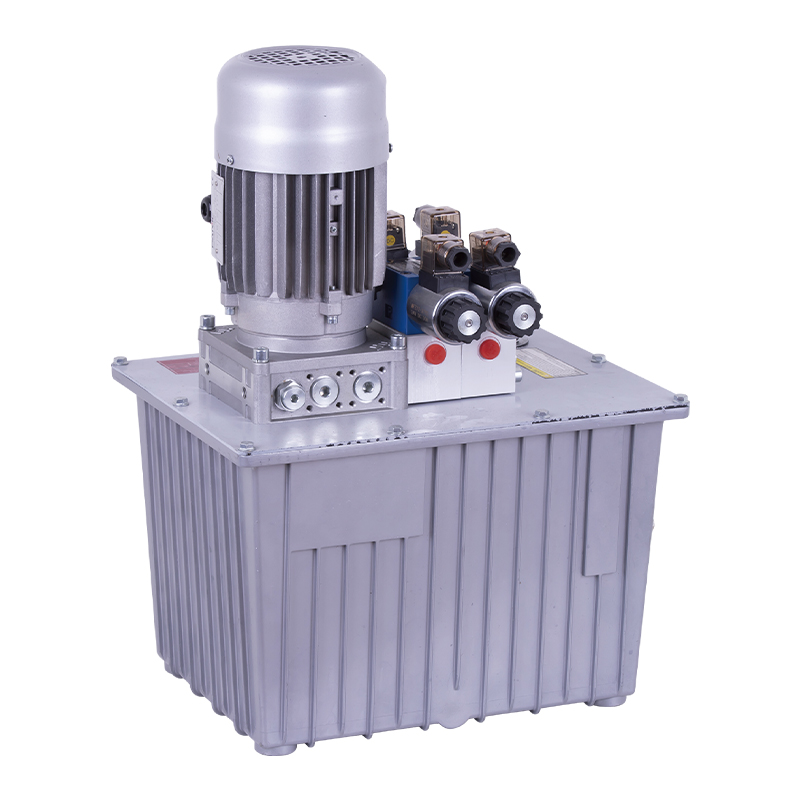
This hydraulic power unit is specially designed for a double-acting oil cylinder system, which is integrated by a high-pressure gear pump, an AC motor...
See Details
This hydraulic power unit is specially designed for hydraulic cargo elevators and is integrated with a high-pressure vane pump, AC Oil immersion motor...
See Details
The V3068 hydraulic valve group is an electric check valve group designed for hydraulic systems. It is mainly used to prevent the backflow of media, e...
See Details
ET series hydraulic lifting platform valve group is specially designed for various hydraulic lifting platforms. It can accurately control the lifting ...
See Details
The relief valve is the core component for controlling pressure in the hydraulic system. It can maintain the stability of the system pressure and prev...
See Details
The hydraulic solenoid valve is a key component in the hydraulic system that controls the opening and closing or reversing of the hydraulic oil passag...
See Details
No. 12 Tongji Road, Simen Town, Yuyao City

+86-0574-62130352
+86-18905846028

+86-0574-62130353

Copyright© Ningbo Panic Hydraulic Technology Co., Ltd. All Rights Reserved. China Hydraulic Power Units Manufacturers

