


 English
 中文简体
 русский
Portable stacker power unit
Cat:DC series hydraulic power unit
This portable stacker hydraulic power unit is designed for portable stackers and integrates a high-pressure gear pump, a permanent magnet DC motor, a ...
See DetailsContent
A 12.5 cc/rev gear motor on a battery-powered scissor lift is asked to hold a 700 kg platform at height. The motor is new, the pump is new, and the platform still sinks 6 mm a minute while the oil temperature climbs past 70 °C after twenty minutes of running. In most of the field cases that look like this, the motor is innocent. The hydraulic motor control valve group sitting between pump and motor is the part that decides whether the load stays put: the directional spool, the counterbalance setting, the relief spring, and the way return flow gets throttled.
This guide is written for the people who have to specify, buy, or fix that valve group. It starts with the direct answer, then works through circuit behaviour, valve types, the arithmetic that sizes a valve, spool centres, power unit matching, and the fault signatures that tell you which element is actually failing.
A hydraulic motor control valve decides four things about a rotary actuator: which direction it turns, how fast it turns, how much torque it can build before it stalls, and what the load does the moment the command stops. On a working machine, that control is almost never one part. It is a stack of elements, and each one answers a different question.
Leave one of those out and the symptom appears somewhere else. Skip the make-up check and the motor inlet pulls a vacuum on a lowering move, which shows up as a growl, then as pitting on the motor's internal surfaces three months later. Fit a relief valve that is set too high because the machine occasionally peaks at 210 bar, and the first cold morning turns that spike into a cracked housing.
A cylinder is normally held by a closed centre or a pilot check. A motor can be turned by the load, and once it is turning, it produces flow instead of consuming it. That single fact changes the pressure on both ports, the heat balance of the circuit, and the failure mode of every valve in the stack. It is why a valve group lifted from a cylinder application so often disappoints on a motor drive.
On a lift motor with a gravity load, there are two workable throttling positions and they are not equivalent. Throttling the return line, usually called meter-out, stops the motor from running away, but it also raises the pressure on the motor outlet. Every bar of that extra pressure leaks past the spool lands and the motor's internal clearances, and leakage at pressure becomes heat. On a typical 20 L/min circuit, holding an extra 60 bar on the outlet can put roughly 1 kW of energy into the oil as heat, which is enough to take a 60 litre reservoir up by more than 20 °C in half an hour if the cooling is marginal.
Throttle the inlet instead, meter-in, and the same load behaves like a runaway brake: the motor accelerates until the back-pressure in the return line happens to balance the load. That is not a tuning problem, it is a physics problem, and it is why lowering circuits are almost always meter-out or counterbalance controlled, with the meter-in setting used only for trimming the raise speed.
The second difference is make-up flow. When a tailboard or a stacker mast comes down under gravity, the motor is driven by the load and needs more oil on its inlet than the main pump is delivering. Without a check valve that lets return oil back into that inlet, the port pressure drops below atmospheric and the oil releases dissolved air. Cavitation damage follows quickly. Understanding where oil actually travels during operation, including which line is under pressure and which is returning, is the first step in diagnosing these circuits; a useful background read is the direction of the oil circuit during power unit operation.
The third difference is duty. A motor may turn continuously for an hour at a pressure that would only appear for ten seconds in a cylinder application. Continuous operation at 80% of the valve's rated pressure is normal for a motor; for a cylinder circuit it is unusual. Valve selection, coil temperature and filtration all have to be judged against that continuous duty rather than against a peak.
Treat the control valve group as a system, not a shopping list. The table below shows the elements that appear most often on motor circuits, the setting range that is normal for each, and the failure signature that points back to it.
| Element | What it controls | Typical size or setting | How it fails |
|---|---|---|---|
| Four-way directional spool, NG6 or NG10 | Direction, stop, neutral circulation | 250 bar working, 40 to 60 L/min on NG6 | Spool sticking from varnish or cold oil |
| Proportional directional valve | Ramped acceleration, adjustable speed | Hysteresis 1 to 3%, needs clean oil | Contamination, drifting command current |
| Pump-side relief valve | Maximum system pressure | Set 10 to 15% above working pressure | Setting creep, chatter, silent dumping |
| Counterbalance valve | Holding and controlled lowering | Roughly 1.3 times load pressure, pilot ratio 3:1 | Drift, hunting on descent |
| Brake release valve | Opening a spring-applied brake | Pilot pressure around 15 to 25 bar | Brake drag, coil and oil overheating |
| Compensated flow control | Constant motor speed as load varies | 2 to 30 L/min cartridges | Compensator clogged, speed falls under load |
| Make-up check valve | Refilling the motor inlet on overrun | Cracking pressure 0.3 to 1 bar | Noise, aeration, motor surface damage |
| Return line filter | Cleanliness reaching the spool clearances | 10 micron for proportional, 25 micron for on-off | Bypass opens unnoticed after cold starts |
The backbone of most mobile and industrial motor circuits is still a solenoid-operated directional valve with a tandem or closed centre, chosen for its coil voltage and neutral behaviour rather than for anything exotic. Varnish and cold oil are its two main enemies, and both of them come from the circuit rather than the valve itself.
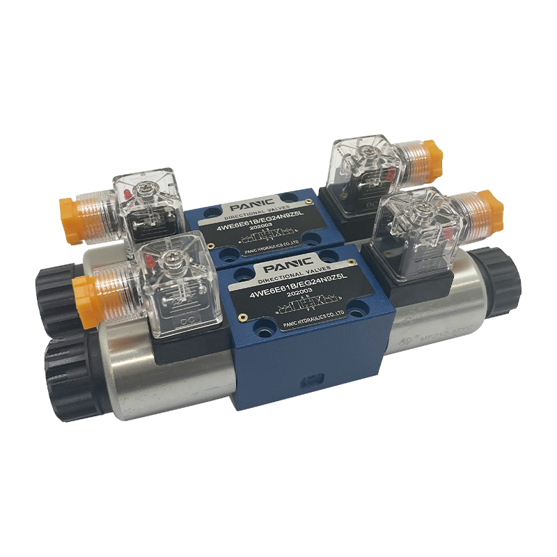 Hydraulic Solenoid ValveThe hydraulic solenoid valve is a key component in the hydraulic system that controls the opening and closing or reversing of the hydraulic oil passage through electro...View Product →
Two pieces of arithmetic settle most arguments about valve size before anything is ordered. The first gives shaft torque, the second gives shaft speed.
Work an example. A 10 cc/rev motor supplied at 20 L/min turns at 2,000 rpm. If the pressure drop across it is 180 bar, theoretical torque is 180 × 10 ÷ 62.8, which comes to about 28.6 Nm, and roughly 26 Nm at the shaft once 90% mechanical efficiency is allowed for. Now size the valve: the main stage has to pass 20 L/min without adding more than a couple of bar of pressure drop, the relief has to be set above the highest working pressure the machine will see, and the return path has to carry the same 20 L/min plus any case drain flow.
| Parameter | Practical target | Why it matters |
|---|---|---|
| Continuous working pressure | 70% of valve rating, so about 175 bar on a 250 bar valve | Leaves headroom for shock and braking peaks |
| Relief setting | 10 to 15% above maximum working pressure | Too low causes dumping and heat, too high endangers housings |
| Oil viscosity at working temperature | 16 to 40 cSt, with 32 cSt as a comfortable middle | Thick oil slows response, thin oil increases internal leakage |
| Cleanliness | ISO 4406 18/16/13 for proportional, 20/18/15 for on-off | Spool clearance is measured in single microns |
| Reservoir temperature | 40 to 55 °C steady state | Every 10 °C above this roughly halves seal life |
| Internal leakage of a healthy spool | Tens of ml/min on an NG6 at 100 bar | A worn spool can pass ten times that and stall a holding circuit |
When a machine needs repeatable speed under changing load, a fixed directional valve plus a throttle cannot deliver it. The compensation has to be built into the valve: a proportional element with current ramps, or a pressure-compensated flow control ahead of the main stage.
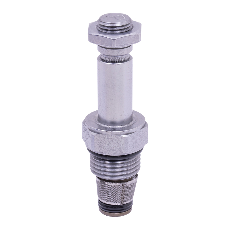 Power Unit Proportional ValveProportional valve is a key component for realizing continuous and precise control of flow or pressure in hydraulic system. It can adjust output parameters in proporti...View Product →
The centre condition of the main spool decides what happens in neutral, and on a motor circuit it is a safety decision as much as a hydraulic one. A closed centre traps oil in both motor lines and lets the load sit on trapped pressure, which then leaks away through the spool lands. An open centre connects both lines to tank, so the motor is free to be turned by the load unless something else holds it. A tandem centre circulates pump flow to tank while keeping the motor lines blocked, which is why it is the common choice on battery-powered equipment where wasted pump flow is wasted battery.
Holding is normally delegated to a counterbalance valve. Its spring setting is usually around 1.3 times the pressure the load generates on the motor port, and it is opened by pilot pressure from the opposite line at a ratio such as 3:1 or 4.5:1. Get those two numbers wrong and you see one of two symptoms: set too low, the load creeps down; set too high, the pump has to build a lot of pressure before the load moves, and the descent turns jerky because the valve opens and closes in cycles.
A vertical axis that drifts more than 2 to 3 mm per minute under a static load is usually losing oil past the spool lands or the counterbalance seat rather than leaking at the motor shaft seal. The quickest proof is to cap the motor lines at the valve and time the drift again: if the axis still moves with the ports capped, the fault is in the motor or the brake, not in the valve group.
A 700 kg platform descending 1 metre releases about 6.9 kJ of potential energy. If the descent takes four seconds, that is roughly 1.7 kW that the hydraulic circuit has to absorb and eventually reject as heat. A motor-port relief valve set at 1.3 to 1.5 times working pressure converts that energy deliberately, in a controlled place, instead of letting it spike through hoses and fittings. Machines without it tend to develop a habit of blowing the hose that looks least convenient to replace.
The valve group does not exist on its own; it hangs off a power unit, and the power unit's supply characteristics decide half of the valve choice. AC power units run fixed or semi-fixed equipment such as scissor lifts, boarding bridges, machine tool clamping and pipe cutting machines, where a mains supply is available and duty can be long. DC power units serve battery equipment: pallet trucks, stackers, tailboards, dump trailers and mobile lifting platforms. Oil-immersed and silent power units cover lifting columns, parking systems, cargo lifts and roadblock installations, where noise limits and installation depth drive the design more than flow rate does.
Two practical points follow from that. First, coil voltage and coil power have to match the supply: a typical 24 V DC directional coil on an NG6 valve draws on the order of 26 to 30 W, which is not trivial when the battery also has to run the pump motor and an intermittent duty cycle applies. Second, the return path back to a compact reservoir has to be short and unrestricted. Valves mounted directly on the power unit with an integrated manifold block avoid long return lines, and the manifold also removes a dozen potential leak points.
For machines where the valve group is specified together with the power unit, cylinder or motor, it is worth working with a supplier who builds the whole set. The range of AC, DC and oil-immersed hydraulic power units built for lifting platforms, stackers, tailboards, machine tools and lifting columns is a reasonable starting point for that kind of matched specification.
Most complaints about motor control valves arrive as one of six symptoms. The table below links each symptom to the element that usually causes it and to the first check that separates a valve fault from a circuit fault.
| Symptom | Most likely cause | First check |
|---|---|---|
| Vertical axis creeps when stationary | Spool land leakage or counterbalance seat wear | Cap the motor ports at the valve and time the drift |
| Oil overheats only while the motor turns | Meter-out throttling or a relief dumping continuously | Compare return line temperature with reservoir temperature |
| Motor growls or rattles on lowering | Cavitation because make-up flow is missing | Inspect the anti-cavitation check and its spring |
| Sluggish response on cold start | Oil viscosity far above the working range | Check the viscosity grade and whether a heater is fitted |
| Speed drops as load rises | No pressure compensation in the speed control element | Confirm the valve type against the duty required |
| Hard stop, hose jump on deceleration | No motor-port relief or cushioning | Measure the peak pressure during a full-speed stop |
Overheating deserves one extra note. A relief valve that creeps 20 bar lower than its setting will quietly dump pump flow for most of the working cycle. The machine still functions, which is why the fault survives for months until the oil darkens and the seals harden. If the return filter housing is noticeably hotter than the reservoir, check the relief before blaming the cooler.
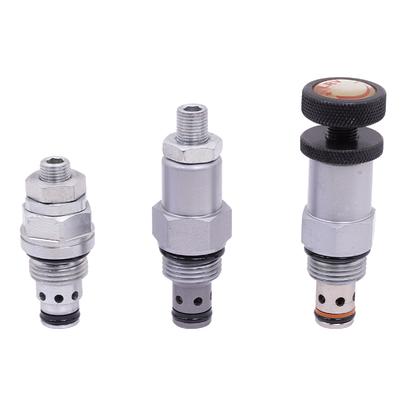 Power Unit Relief ValveThe relief valve is the core component for controlling pressure in the hydraulic system. It can maintain the stability of the system pressure and prevent equipment dam...View Product →
Work through these points in order and most specification mistakes disappear before the purchase order is written.
Four things: direction of rotation, rotational speed, the maximum torque available before the motor stalls, and the behaviour of the load when the command is removed. In practice those functions are split across a main directional or proportional stage, a relief valve, a load-holding element such as a counterbalance valve, and make-up checks for overrunning conditions.
Sometimes, but only if the circuit is completed properly. The main stage itself is often the same hardware, so the extra risk sits in what surrounds it: a counterbalance valve for holding, make-up checks so the motor inlet never pulls a vacuum, and a motor-port relief to absorb braking pressure. A cylinder valve stack with none of those will work on the bench and fail in service.
Drift comes from leakage, and there are only three places for it to happen: past the spool lands, past the counterbalance seat, or inside the motor itself. Cap the motor lines at the valve and time the movement again. Movement with the ports capped points to the motor or a mechanical brake; movement only when the valve is connected points to the valve group.
Set the pump-side relief 10 to 15% above the highest pressure the machine reaches in normal work, and make sure the valve's continuous rating still leaves headroom above that. Where a load can drive the motor, add a separate relief across the motor ports, typically at 1.3 to 1.5 times working pressure, so braking energy is converted in a controlled place rather than in the hoses.
A proportional element is comfortable at ISO 4406 18/16/13, with filtration rated 10 micron absolute and a bypass indicator so a clogged element cannot quietly open. Plain on-off directional spools tolerate 20/18/15 with 25 micron filtration. Viscosity should sit between 16 and 40 cSt at working temperature, with around 32 cSt as the practical target.
Control the return flow, not the supply. Use meter-out throttling or a counterbalance valve with a pilot ratio matched to the available pilot pressure, and provide make-up oil for the inlet side. On fast descents with heavy inertia, an overspeed sensing valve that closes when return flow exceeds a set value is the last line of defence.
Steady-state reservoir temperature of 40 to 55 °C keeps viscosity in range and seal life predictable. Above 70 °C, internal leakage climbs, spool response slows and the varnish that causes sticking spools begins to form. If a motor circuit only overheats while the motor is running, look at return-line throttling and relief dumping before adding cooling capacity.
A hydraulic motor control valve group is a small assembly with an outsized effect on how a machine feels to the operator: whether a platform settles or holds, whether a stacker descends smoothly or shudders, whether the oil stays at 50 °C or climbs to 80 °C. Get the four jobs right, direction, speed, torque limit and holding, and add make-up flow and filtration for the duty the machine actually sees, and most of the field failures described here simply never appear.
Start from the load, work out the numbers, then choose the elements that match those numbers rather than the elements that happen to be on the shelf.
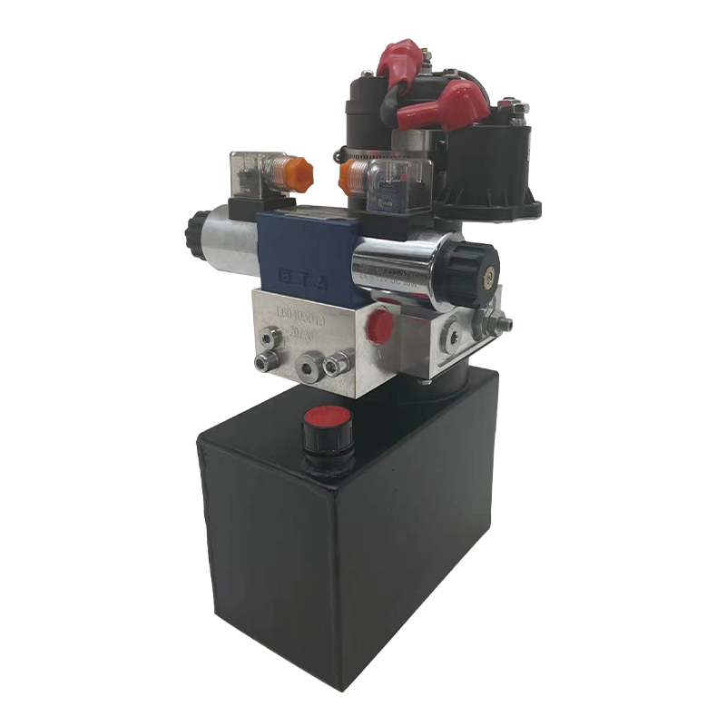
This portable stacker hydraulic power unit is designed for portable stackers and integrates a high-pressure gear pump, a permanent magnet DC motor, a ...
See Details
This DC single acting power unit is designed for mobile hydraulic lifting platforms. It provides an efficient and reliable hydraulic power solution th...
See Details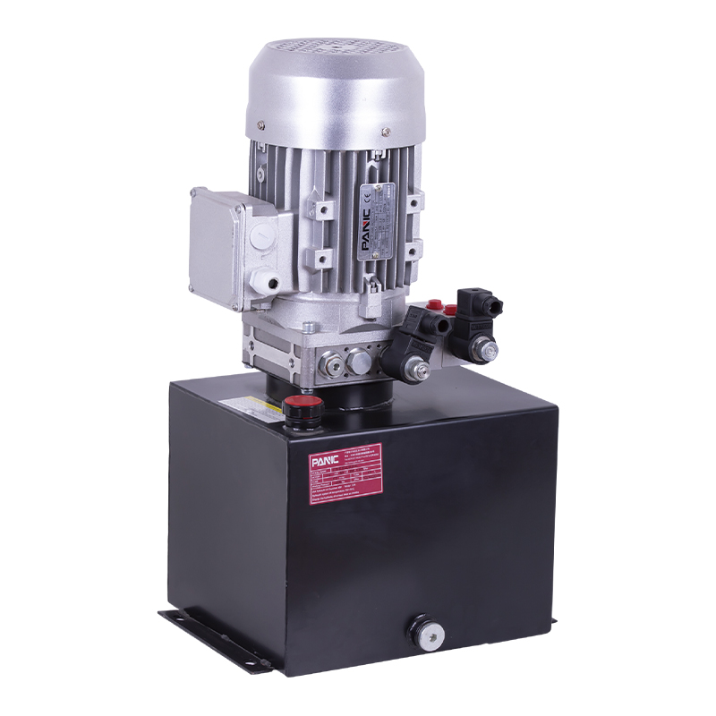
This hydraulic power unit is designed for scissor lifts and integrates a high-pressure gear pump, AC motor, center valve block, cartridge valve and oi...
See Details
This hydraulic power unit is specially designed for the clamping cylinder of the machine, too. It is integrated by a high-pressure gear pump.AC motor,...
See Details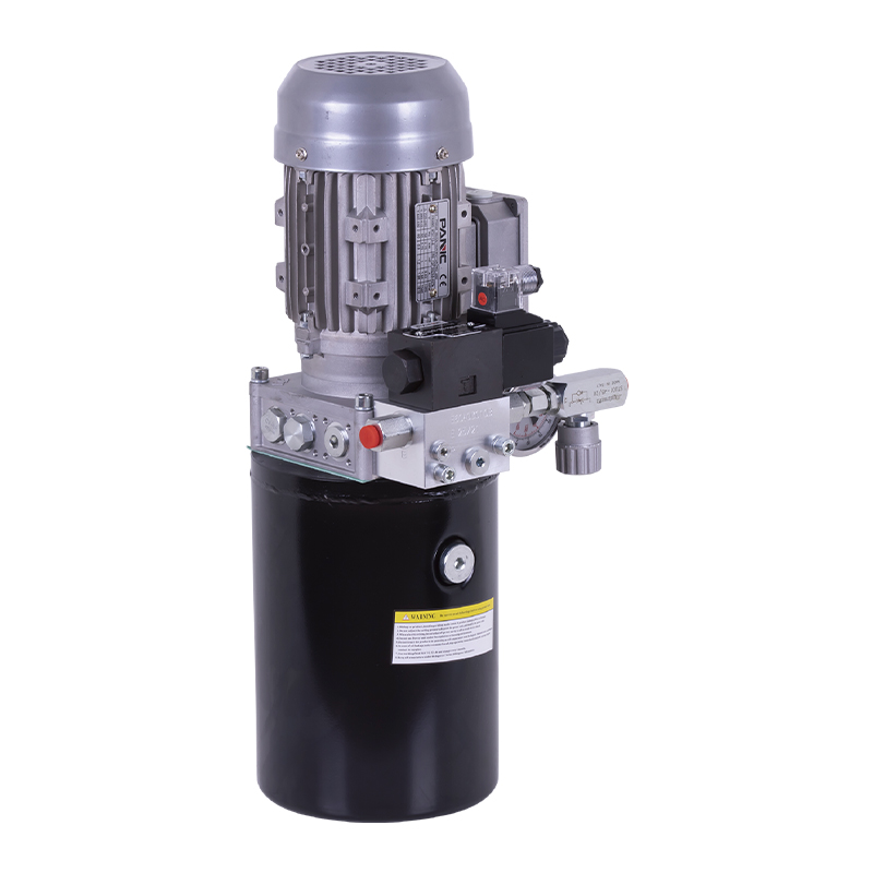
This hydraulic power unit is specially designed for the rotary feed of the pipe cutting machine. It is integrated by a high-pressure gear pump, an AC ...
See Details
The V3068 hydraulic valve group is an electric check valve group designed for hydraulic systems. It is mainly used to prevent the backflow of media, e...
See Details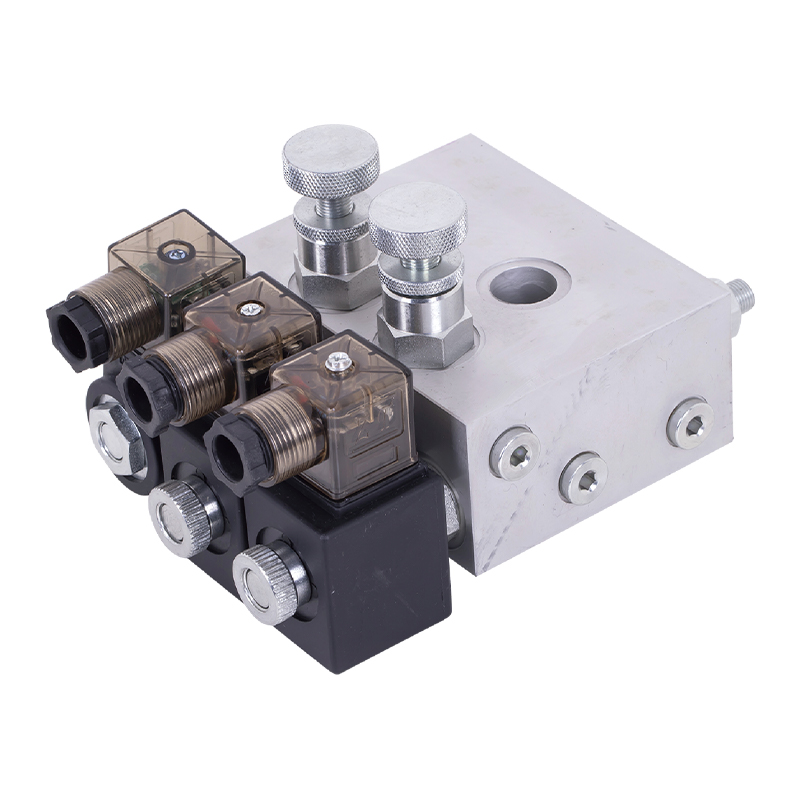
The tailgate hydraulic valve group is the core control component of the truck tailgate hydraulic system, which is designed to provide precise control ...
See Details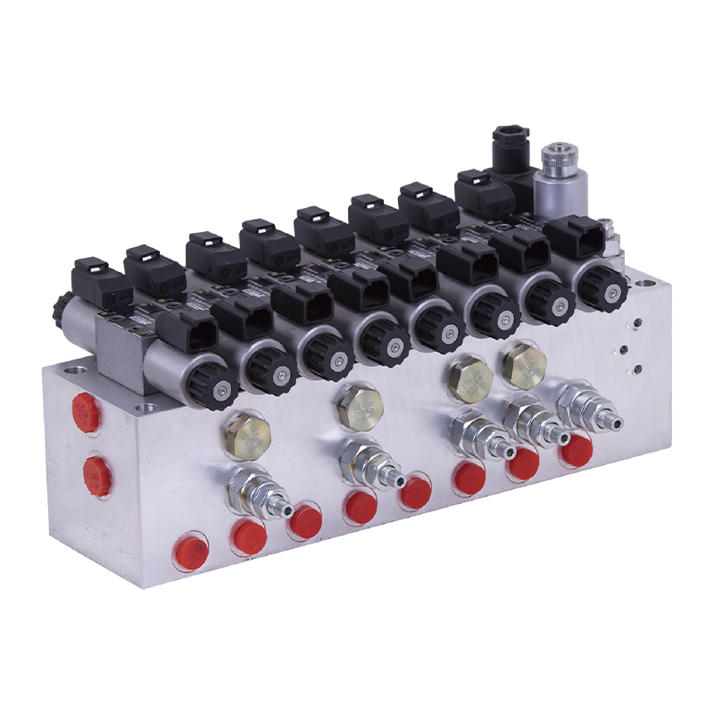
The modular hydraulic valve block uses modular integrated design to accurately combine multiple hydraulic valves, greatly simplifying the system pipel...
See Details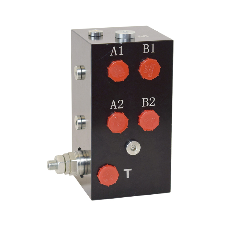
The hydraulic valve block centrally installs various hydraulic valves through the internal precision flow channel, solves the problems of bloated and ...
See Details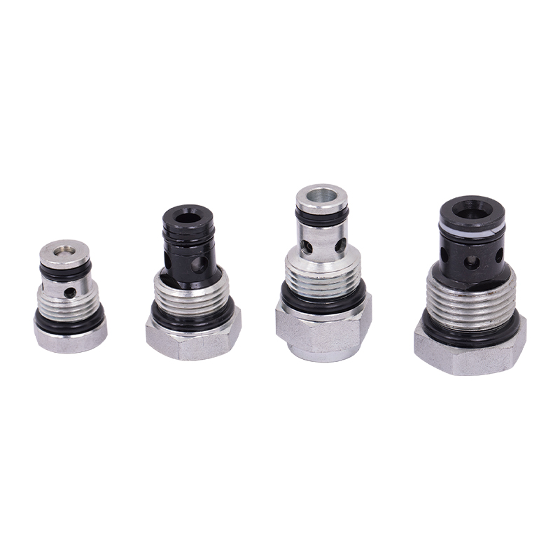
The power unit check valve (also called non-return valve) is a key component for controlling the one-way flow of fluids. It can prevent hydraulic oil,...
See Details
No. 12 Tongji Road, Simen Town, Yuyao City

+86-0574-62130352
+86-18905846028

+86-0574-62130353

Copyright© Ningbo Panic Hydraulic Technology Co., Ltd. All Rights Reserved. China Hydraulic Power Units Manufacturers

