


 English
 中文简体
 русский
Brushless motor hydraulic power unit
Cat:DC series hydraulic power unit
This hydraulic power unit is controlled by a brushless motor and can be divided into external and internal drives based on power. It is integrating co...
See DetailsContent
A hydraulic flow divider decides whether two cylinders lift a platform evenly, whether a drill carriage advances straight, and whether the two drive motors on a mobile machine turn at the same speed. Its entire job is to take the flow delivered by one pump and split it into two or more streams at a fixed ratio. This article explains the working principle, compares the main types, gives you a concrete selection checklist, covers crossport relief valves, and walks through common problems so you can specify and maintain flow dividers with confidence. If you only remember one thing, remember this: for any application that needs synchronized or proportional movement, a correctly sized flow divider usually delivers the result at a fraction of the cost of adding a second pump.
A hydraulic flow divider is a flow-control device installed downstream of a pump. It accepts the full pump flow at its inlet and distributes that flow to two or more outlet circuits according to a fixed or adjustable ratio. The most common configuration delivers 50 percent to each of two outlets, but three-section and four-section units are standard, and units with unequal ratios can be built to order.
It is important to distinguish a flow divider from other components:
When a single pump feeds multiple actuators, unequal loads naturally cause the lightly loaded actuator to move first and fastest. A flow divider forces each branch to receive the same volume of oil over time, so the actuators move in step despite different loads. That is the reason flow dividers appear in scissor lifts, aerial work platforms, hydraulic presses, and slurry tankers. Understanding where the divider sits in the circuit is easier when you review the working principle of a hydraulic system first.
The gear-type flow divider is the best place to start because it is the most widely used in industrial and mobile hydraulics. Picture two fixed-displacement gear sets mounted back to back in one housing, with both gear shafts connected on a common drive shaft. Pressurized oil from the pump enters a common inlet passage and flows into both gear sections simultaneously. From there it exits through separate outlet ports. Because the gear sections are mechanically locked to the same shaft, they must rotate at exactly the same speed. Each output therefore delivers a fixed percentage of the incoming flow, set by the displacement of that gear section.
Consider a unit with two identical gear sections. The pump delivers 12 L/min to the inlet, and each outlet receives 6 L/min no matter how much the pressure at each outlet differs. If the cylinder on outlet port A encounters a heavier load, its pressure rises and it tends to resist the flow. The gear set in section A tries to slow down, and the gear set in section B tries to speed up. But the common shaft transfers torque from the less-loaded section to the more-loaded section, so both sections continue rotating at exactly the same speed. The flow division stays accurate within about 2 to 3 percent.
This is called pressure-compensated flow division, and it is the key advantage of gear-type and motor-type dividers over simple orifice splitters. The same principle allows the unit to act as a flow combiner: push oil into both outlet ports, and the internal shaft equalizes the two inlet flows into one combined outlet flow.
One important detail: if one outlet is completely blocked, the pressure in that section rises until the common shaft stalls or the system relief valve opens. That is why flow dividers are often supplied with integral crossport relief valves, covered in a dedicated section below.
Not all flow dividers use gears, and the type you choose changes the accuracy, pressure capability, and cost. Here are the four main categories.
| Type | Typical accuracy | Max pressure | Sections available | Best suited for |
|---|---|---|---|---|
| Gear-type | ±2-3% | 250-300 bar | 2 to 6 | Lifting platforms, clamping, synchronized cylinders |
| Motor-type | ±3-5% | 250 bar | 2 to 4 | High-flow mobile circuits |
| Spool-type | ±1-2% | 350 bar | 2 to 4 | Precision metering, feed drives |
| Orifice/restrictor | ±10% or more | 400 bar (valve rating) | 2 or more | Non-critical lubrication circuits |
Since gear-type dividers dominate the market, it pays to understand their construction. Each section consists of a gear pair, a housing cavity, and a set of bushings that form the bearing and sealing surfaces. The sections are stacked and bolted together in one housing, and a common drive shaft passes through all of them. Many manufacturers also offer an optional crossport relief valve block that connects the outlet ports to each other.
A typical 20 L/min gear-type divider with two equal sections weighs roughly 8 to 12 kg depending on the housing material and port size. Aluminum housings keep weight down, but cast-iron housings tolerate higher pressure spikes.
When you open a datasheet for a flow divider, you will see around six important numbers. Here is what to check first:
A common mistake is choosing a divider by inlet port size alone. The inlet port tells you nothing about the displacement ratio or the accuracy class. Always work from the hydraulic data, not from the thread size.
Flow dividers appear wherever a single pump must serve multiple paths reliably. Their most familiar role is keeping two or more actuators in step.
A typical 4-post lifting platform uses two cylinders at opposite corners. Without a divider, the heavier side always rises first and the platform tilts. A gear-type divider with two equal sections ensures both cylinders receive the same flow, keeping the platform level within the cylinder leakage tolerance. If you are building this kind of application, the power unit choice is as important as the divider itself. A lifting platform powered by a dedicated AC power unit with a manifold-mounted flow divider is usually the simplest construction.
Tailboard lifts, dump trailer hoists, and aerial work baskets use dividers to share pump flow between steering and lifting circuits. DC-powered power units on truck tailboards frequently work with a divider because vehicle battery power limits pump size, but the tailboard must still rise evenly on both sides.
Clamping systems with multiple hydraulic clamps close each clamp at the same rate when fed through a flow divider, reducing vibration and work-piece distortion.
Gear-type dividers split a small pump flow to multiple lube points, and the compact construction handles high outlet resistance.
In systems where two hydraulic motors drive one belt, a flow divider roughly synchronizes the motors until mechanical belt tension balances the speeds.
 Lifting platform power unitDesigned for hydraulic lifting platforms, this lifting platform power unit integrates a high-pressure gear pump, AC motor, center valve block, cartridge valve and oil ...View Product →
A gear-type flow divider behaves as a positive-displacement machine. If one outlet is blocked or its actuator stalls, the gear section in that branch continues to receive flow until the pressure rises to the pump relief setting or the divider fails. Crossport relief valves connect the two outlet passages to one another. When the pressure in one branch exceeds the valve setting, the valve opens and allows oil to pass from that branch into the neighboring branch, so the stalled section cannot overpressurize.
The relief valves also protect against pressure intensification. If a suspended load pushes a cylinder faster than the divider feeds it, that cylinder port pressure drops and the opposite port pressure rises. A crossport relief limits the spike before it damages hoses or seals.
Typical settings range from 20 to 50 bar above the maximum working pressure of the corresponding branch. Never set it above the pressure rating of the actuator hose or cylinder seal.
For circuits that use a flow divider together with a power unit relief valve, keep the power unit relief setting above the crossport setting. Otherwise the crossport valve never opens and offers no protection. Some divider manufacturers build relief valves into the divider body; others offer a separate sandwich plate. For a power-unit engineer, a divider with integral crossport relief is usually the easiest to plumb. When you assemble the valve stack for a mobile power unit, a compatible power-unit relief valve on the main manifold protects the whole circuit at the pump output.
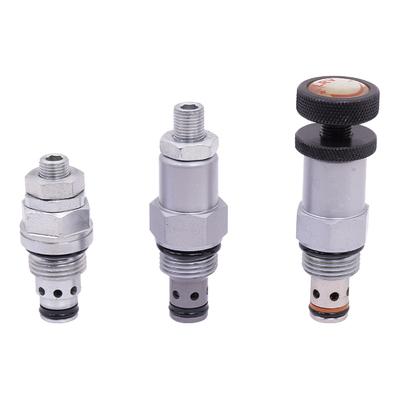 Power Unit Relief ValveThe relief valve is the core component for controlling pressure in the hydraulic system. It can maintain the stability of the system pressure and prevent equipment dam...View Product →
The flow divider does not create energy; it distributes the energy that the power unit supplies. So the first step in sizing is to look at the pump output of your power unit.
Example: a DC power unit with a gear pump delivers 8 L/min at 150 bar. A two-section equal flow divider sends 4 L/min to each branch. Each cylinder with a 40 mm bore and 800 mm stroke moves at roughly 0.04 m/s, ignoring cylinder friction losses. The pressure needed at each branch depends on the load, but the power unit relief valve determines the maximum pressure the divider will see.
For mobile applications, DC series power units are frequently paired with two-section dividers to run a pair of tailboard cylinders. A DC double-acting power unit with a built-in valve scheme can be combined with an external flow divider when two cylinders have to remain synchronized through both the extend and retract strokes. Note that a flow divider divides flow in one direction only unless it has a combiner function; check the datasheet for bidirectional capability.
 DC double acting power unitThis DC double acting power unit is an integrated hydraulic system designed for various equipment that requires efficient hydraulic drive. It is suitable for double-ac...View Product →
Flow dividers are simple and durable, but they still fail when oil is contaminated, pressures are set too high, or the unit is oversized. The table below lists the issues you are most likely to see in a workshop or on a machine site.
| Symptom | Likely cause | Correction |
|---|---|---|
| Uneven movement of two cylinders with no load | Worn or damaged gear sections; internal leakage | Measure outlet flows under pressure; replace divider |
| Both branches slow | Pump flow insufficient; divider oversized | Check pump delivery at working pressure; recalculate size |
| Loud whine or overheating | High pressure drop; wrong oil viscosity; internal wear | Check viscosity; verify pressure drop; inspect divider |
| Cylinder drift after stopping | Internal leakage across divider sections; actuator valve leak | Test with blocked ports; repair or replace divider |
| No flow from one outlet | Blocked port; broken shaft between sections | Inspect, clean, and replace the divider |
A flow divider takes one inlet flow and splits it into multiple outlet flows. A flow combiner takes multiple inlet flows and merges them into one outlet flow. Many gear-type and motor-type dividers operate both ways, but you must check the datasheet because some models are directional.
Not with an equal-section divider. Different bore sizes consume different volumes per millimeter of stroke, so they need different flows. Use a divider with unequal section ratios or a closed-loop proportional valve in that case. For identical cylinders, an equal-section divider works well.
For a new unit at rated flow and pressure, division accuracy is typically within plus or minus 2 to 3 percent. This value degrades as the gear sections wear and internal leakage increases, especially when operating at low flow.
It connects the two outlet ports through a set of relief valves. When pressure in one branch exceeds its set point, the valve opens and dumps oil to the other branch, preventing pressure spikes during load overrun or actuator stall.
Start with the pump flow and the number of branches. The inlet flow must match the rated flow of the divider. The total of outlet flows equals the inlet flow minus internal leakage. Check the pressure rating against your relief valve setting, choose the port standard, and decide if you need crossport relief and unequal ratio sections.
A hydraulic flow divider is a simple component, but it solves a problem that would otherwise require a second pump, an electronic synchronization system, or a costly feedback control loop. For synchronized movement, proportional flow sharing, and reliable operation under unbalanced loads, a gear-type divider with integral crossport relief is the most practical starting point. Spec it from the pump flow, set the reliefs correctly, keep the oil clean, and it will work quietly for years.

This hydraulic power unit is controlled by a brushless motor and can be divided into external and internal drives based on power. It is integrating co...
See Details
This boarding axle power unit is specially designed for fixed boarding ramps and integrates a high-pressure gear pump, an AC motor center valve block,...
See Details
Designed for hydraulic lifting platforms, this lifting platform power unit integrates a high-pressure gear pump, AC motor, center valve block, cartrid...
See Details
The hydraulic power unit is specially designed for the integrated shallow buried hydraulic lifting column, It integrates a bidirectional gear pump, AC...
See Details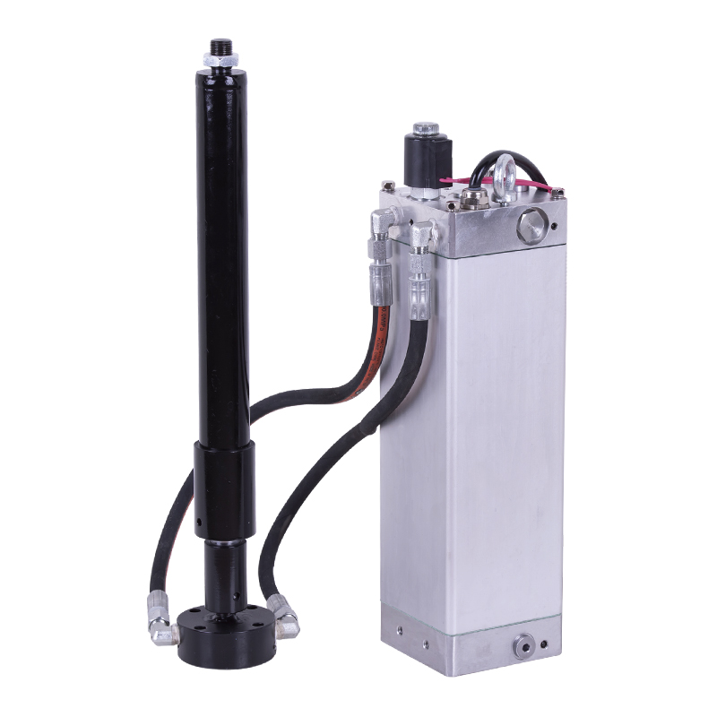
This hydraulic power unit is tailor-made for split shallow buried hydraulic lifting columns. It integrates a bidirectional gear pump, AC oil-immersed ...
See Details
This hydraulic power unit is specially designed for the three-dimensional parking garage and is integrated by a high-pressure vanepump, an AC oil imme...
See Details
ET series hydraulic lifting platform valve group is specially designed for various hydraulic lifting platforms. It can accurately control the lifting ...
See Details
The relief valve is the core component for controlling pressure in the hydraulic system. It can maintain the stability of the system pressure and prev...
See Details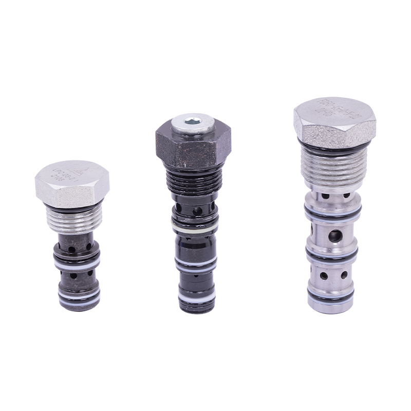
The cartridge hydraulic control check valve controls the on/off and flow direction of the hydraulic oil to start, stop, change direction and lock the ...
See Details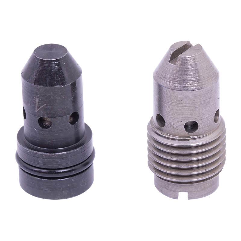
The pressure compensation valve is a key component in the hydraulic system to maintain flow stability. It can automatically adjust the valve opening w...
See Details
No. 12 Tongji Road, Simen Town, Yuyao City

+86-0574-62130352
+86-18905846028

+86-0574-62130353

Copyright© Ningbo Panic Hydraulic Technology Co., Ltd. All Rights Reserved. China Hydraulic Power Units Manufacturers

