


 English
 中文简体
 русский
Hydraulic tailboard power unit
Cat:DC series hydraulic power unit
This hydraulic power unit is specially designed for the hydraulic tail plate. The vehicle tail plate hydraulic power unit is a power unit used for the...
See DetailsContent
A hydraulic clamp is a workholding device that uses pressurized hydraulic fluid to create and hold clamping force on a workpiece. In CNC machining and other manufacturing processes, hydraulic clamps keep parts rigidly in position during milling, drilling, turning, and grinding, so that dimensional accuracy and surface finish remain consistent across every piece in a production run.
A typical hydraulic clamping system has three core elements: a hydraulic power unit that produces pressurized oil flow, clamping cylinders or actuators that convert that pressure into mechanical holding force, and a control circuit with valves, hoses, and fittings that governs clamping speed, pressure, and timing.
Manufacturers choose hydraulic clamps primarily for repeatability. A manual vise depends on operator strength and feel; a hydraulic clamp applies an identical force on every cycle, removing one of the most frequent causes of machining variation. Hydraulic clamps also deliver far higher force in a compact footprint, which is why they are standard equipment on modern machining centers, transfer lines, and flexible manufacturing systems.
The working principle is straightforward. An electric motor drives a hydraulic pump, usually a gear pump, which draws oil from a reservoir and pushes it through a directional control valve toward the clamping cylinder. As oil enters the pressure port, the piston extends and moves the swing arm or clamp block down onto the workpiece. When the directional valve shifts, oil returns to the tank and the clamp opens.
Most machine tool clamping circuits use double-acting cylinders, which require pressure to clamp and pressure to release. Single-acting versions use a spring return and need pressure in only one direction, making them simpler but slower. The clamping force equals hydraulic pressure multiplied by the effective piston area. A 63 mm bore cylinder at 100 bar, for example, produces about 31 kN before any lever ratio is applied.
One point is often misunderstood: the clamp body does not determine the clamping force. The power unit and the pressure relief valve setting do. That is why selecting the power unit is as important as choosing the clamp itself. To understand how pressure, flow, and directional valves act together inside a circuit, review the working principle of hydraulic systems explained in our industry news.
 Hydraulic Clamping Power Unit for Machine ToolsThis compact power unit maintains stable clamping pressure with a hydraulic lock, features an energy-saving intermittent motor, and offers motor and voltage options for flexible machine tool integration.View Product →
Hydraulic clamps come in several mechanical configurations, each designed for a specific workholding geometry. The most common types found on machine tools and fixtures are described below.
A swing clamp rotates its arm into position above the workpiece and then moves down vertically to clamp. The swing angle is usually 30, 45, or 90 degrees. Swing clamps are the most popular choice for top clamping because they leave the loading area completely open. Available force typically ranges from 5 kN to 50 kN.
These low-profile clamps pull the part down at an angle. They are useful in compact fixtures where stroke length is limited. The clamping force is transmitted through a link mechanism, which also generates a horizontal hold-down effect that prevents the part from lifting during heavy cuts.
Edge clamps approach the workpiece from the side, leaving the entire top surface clear for tool access. Many hydraulic edge clamps combine a horizontal push with a vertical pull-down, which is essential for thin or warpage-prone parts such as aluminum housings and cover plates.
These clamps expand outward from inside a bore or a machined feature. They are ideal for gears, sleeves, and castings that must be located on an internal diameter. The radial expansion centers the part and distributes clamping force evenly around the circumference, reducing distortion on thin-wall components.
Self-centering or fixed-jaw vises with hydraulic actuation are common on palletized machining systems because they can be released and re-clamped automatically without operator intervention. A hydraulic vise typically delivers 10 kN to 60 kN of clamping force and is built for repeated high-throughput cycles.
| Clamp Type | Typical Force Range | Best Application |
|---|---|---|
| Swing clamp | 5-50 kN | Top clamping on machining centers and tombstones |
| Block and link clamp | 3-30 kN | Low-profile fixtures with limited stroke |
| Edge clamp | 2-25 kN | Side clamping with unobstructed tool access |
| Expanding collet and mandrel | 10-80 kN | Internal bore clamping for gears, sleeves, and castings |
| Hydraulic vise | 10-60 kN | Palletized systems and self-centering workholding |
 Hydraulic Cylinder for Clamping and ActuationA versatile actuator converting hydraulic energy into linear motion, built with high-strength materials and precision sealing for reliable clamping and positioning in demanding machine tool applications.View Product →
A hydraulic clamp is only as good as the numbers behind it. When comparing products, check the following parameters against your cutting loads, fixture layout, and cycle time targets.
| Specification | Typical Range | Why It Matters |
|---|---|---|
| Clamping force | 2-80 kN | Determines whether the part stays rigid under cutting load |
| Piston stroke | 5-50 mm | Longer stroke eases part loading in deep fixtures |
| Operating pressure | 70, 140, or 210 bar | Higher pressure allows smaller cylinders for the same force |
| Pump flow rate | 1-20 L/min | Controls clamp open-close speed and overall cycle time |
| Repeatability | ±0.01 to ±0.05 mm | Affects consistency in multi-part or palletized processes |
| Release pressure | Specified for double-acting models | Ensures reliable unclamping on every cycle |
Each clamping technology has a place on the shop floor. The comparison below shows why hydraulic clamps dominate in high-force, high-accuracy machining environments.
| Criteria | Hydraulic | Pneumatic | Mechanical |
|---|---|---|---|
| Force density | High; compact cylinders produce 20-50 kN | Low; cylinders become large above 5 kN | Medium; limited by operator strength |
| Speed and control | Smooth, adjustable speed and force | Fast, but force varies with air pressure | Manual; dependent on operator technique |
| Repeatability | Excellent; identical force every cycle | Good; affected by air compressibility | Poor; operator dependent |
| System footprint | Pump, reservoir, valves, hoses | Compressor, FRL, valves | None |
| Noise level | Moderate | High | Low |
| Cost profile | Higher initial, lower long-term per-part cost | Low initial, higher energy cost | Lowest initial, highest labor cost |
Hydraulic clamps are not limited to one vertical. They appear wherever cutting forces are high, tolerances are tight, or cycle times must be short. The most common sectors include:
The power unit is the heart of the clamping system. It sets the pressure, supplies the flow, and determines how fast your clamps move. Follow these selection steps:
For machines with several clamping zones or additional hydraulic functions, a larger hydraulic station with multiple circuits may be a better fit. Browse the AC series hydraulic power unit catalog to compare pressure, flow, and reservoir configurations.
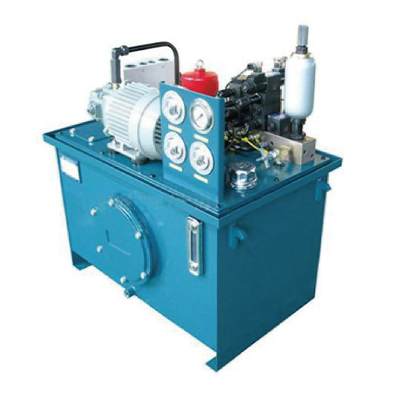 Hydraulic Station for Multi-Circuit SystemsServing as the power heart of hydraulic systems, this station integrates pump, motor, tank, and control valves, offering customizable pressure and flow for stable operation across industrial equipment.View Product →
A hydraulic clamping system will run for years with little attention, but only if installed cleanly and checked regularly. Use these practices as your baseline:
Even well-designed clamping systems develop issues over time. The table below covers the failures machine shops encounter most often.
| Symptom | Likely Cause | Corrective Action |
|---|---|---|
| Clamping force drops during machining | Internal leakage past the piston seal; worn relief valve | Replace seals; reset or replace the relief valve |
| Clamp opens slowly | Flow control set too low; pump output reduced | Increase flow; check pump for wear |
| Oil leaks around the cylinder rod | Damaged rod seal; scored rod surface | Replace the rod seal; polish or replace the rod |
| System runs hot | Low oil level; wrong viscosity; relief set too high | Top up oil; use the recommended grade; reset relief pressure |
| Clamp chatters or vibrates | Air trapped in the circuit; pressure set too low | Bleed the air; increase pressure to the specified level |
Cost is usually the first question from plant managers, and the honest answer is that it depends on the number of clamps, the complexity of the fixture, and the power unit capacity. As an illustrative planning figure, a two-station fixture with four swing clamps and one machine tool hydraulic clamping power unit commonly falls into the USD 4,000 to 9,000 range including hoses and a manifold. A manual fixture with the same number of stations might cost USD 1,500 to 3,000.
The payback calculation changes the picture. If manual clamping takes 2 minutes per part and hydraulic clamping reduces that to 15 seconds, a 50-part daily production run saves about 1.5 hours per day. At a shop rate of USD 50 per hour, that works out to roughly USD 18,000 per year, which means the extra initial investment often pays back in under six months. These figures are planning estimates based on typical mid-size machine shop rates and should be adjusted for your actual labor cost and production volume.
Energy cost is minor. A 2.2 kW power unit operating for a total of one minute per part consumes about 0.037 kWh per part. At standard industrial electricity rates, the energy cost per part is only a fraction of a cent, making the operational cost nearly negligible compared to labor savings.
A hydraulic clamp holds workpieces securely during machining. It converts hydraulic pressure into mechanical clamping force, providing high repeatability and force levels that are difficult to achieve with manual or pneumatic clamps. Typical uses include CNC mills, lathes, grinders, transfer lines, and flexible manufacturing cells.
A practical rule is to size the clamping force at two to three times the maximum expected cutting force. Calculate the cutting force from material type, depth of cut, feed rate, and spindle power, then add a safety margin. For a typical aluminum machining operation with a 5 kN cutting force, plan for 10-15 kN of clamping force per clamp position.
Most hydraulic clamps are rated for 70 to 210 bar. In machine tool workholding, 100-140 bar is the most common range because it balances cylinder size, seal life, and heat generation. Always set the pressure relief valve below the maximum rating of the lowest-rated component in the circuit.
Choose double-acting clamps when automation requires positive unclamping on every cycle. Choose single-acting spring-return clamps when fail-safe clamping is preferred, for example, so that the workpiece stays clamped if hydraulic pressure drops unexpectedly.
ISO VG 32 anti-wear hydraulic oil is the standard choice for indoor machine shop environments. Use ISO VG 46 for warmer ambient temperatures or heavy continuous operation. Whichever grade you choose, maintain the oil cleanliness level recommended by the component manufacturer, typically ISO 4406 class 20/18/15 or better.
Check oil level, leaks, and pressure settings monthly. Change the oil and return-line filter every 2,000 to 3,000 operating hours, or sooner if oil analysis shows contamination. Test the clamping force with a load cell annually to catch internal wear before it causes quality problems.
Hydraulic clamps remain the most dependable way to achieve high, repeatable clamping force in metal cutting. The key to a successful installation is not just the clamp itself, but the complete system: the right clamp configuration, the correct operating pressure, a properly sized power unit, and a disciplined maintenance routine. Start by defining your cutting loads and cycle time targets, then work backward to the cylinder bore, pump flow, and reservoir capacity. That approach will give you a clamping system that runs predictably for years and protects the quality of every part that crosses your machines. If you are planning a new fixture or upgrading an existing line, review our hydraulic power unit product range to find the pressure and flow configuration that matches your workholding needs.
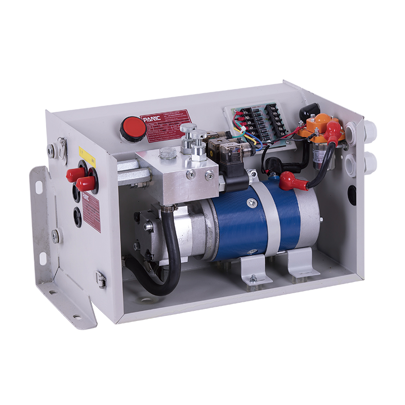
This hydraulic power unit is specially designed for the hydraulic tail plate. The vehicle tail plate hydraulic power unit is a power unit used for the...
See Details
This DC bidirectional pump power unit adopts an integrated design of multiple components such as a bidirectional gear pump, a permanent magnet DC moto...
See Details
This DC single acting power unit is designed for mobile hydraulic lifting platforms. It provides an efficient and reliable hydraulic power solution th...
See Details
This hydraulic power unit is controlled by a brushless motor and can be divided into external and internal drives based on power. It is integrating co...
See Details
This boarding axle power unit is specially designed for fixed boarding ramps and integrates a high-pressure gear pump, an AC motor center valve block,...
See Details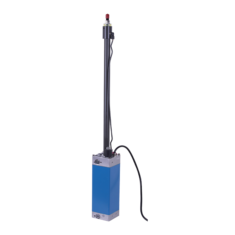
The hydraulic power unit is specially designed for the integrated hydraulic lifting column, which is integrated by a two-way gear pump, an AC Oil imme...
See Details
This hydraulic power unit is designed to meet extreme security needs, especially for critical occasions where large vehicles such as heavy trucks and ...
See Details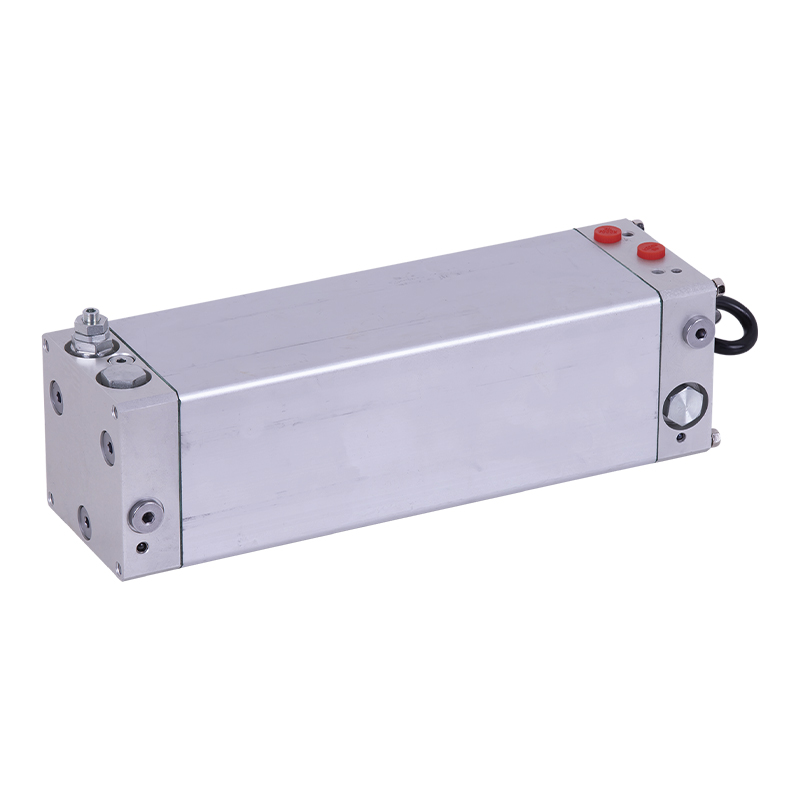
This oil immersed bidirectional pump power unit is designed for various types of mechanical equipment. It integrates a high-pressure bidirectional gea...
See Details
This hydraulic power unit is specially designed for the three-dimensional parking garage and is integrated by a high-pressure vanepump, an AC oil imme...
See Details
Proportional valve is a key component for realizing continuous and precise control of flow or pressure in hydraulic system. It can adjust output param...
See Details
No. 12 Tongji Road, Simen Town, Yuyao City

+86-0574-62130352
+86-18905846028

+86-0574-62130353

Copyright© Ningbo Panic Hydraulic Technology Co., Ltd. All Rights Reserved. China Hydraulic Power Units Manufacturers

