
 English
 中文简体
中文简体 русский
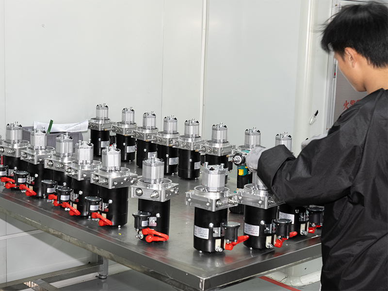
Mini Pallet Truck Hydraulic Power Unit
Cat:DC series hydraulic power unit
This hydraulic power unit is specially designed for all electric pallet truck.It consists of high voltage gear pump,permanent magnet DC motor and cent...
See DetailsContent
A hydraulic system works by using pressurized fluid — almost always oil — to transmit force from one point to another. When a pump pressurizes the fluid, that pressure acts equally in all directions throughout an enclosed circuit. Actuators such as cylinders or motors convert that fluid pressure back into mechanical force or motion. The result is a system capable of moving enormous loads with precise control, using relatively compact components.
This principle is grounded in Pascal's Law, which states that pressure applied to a confined fluid is transmitted undiminished in all directions. A force of just 100 N applied over 1 cm² creates a pressure of 10 MPa — and that same pressure acting on a 100 cm² cylinder face delivers 100,000 N of output force. That force multiplication is exactly why hydraulics dominate heavy industry, construction equipment, aerospace, and manufacturing.
Every hydraulic system, from a simple shop press to a complex aircraft landing gear mechanism, shares the same fundamental architecture: a power source, a pump, a fluid reservoir, control valves, actuators, and a return path. Understanding each element explains why hydraulic systems are so reliable and why they remain the preferred solution when high force density and controllability are both required.
The Hydraulic Power Unit (HPU) is the heart of any hydraulic system. It is a self-contained assembly that generates, conditions, and supplies pressurized hydraulic fluid to the rest of the circuit. A standard Hydraulic Power Unit combines a fluid reservoir, an electric motor or combustion engine, a hydraulic pump, a pressure relief valve, a filter, and instrumentation — all mounted on a single baseplate or frame.
When the motor drives the pump, fluid is drawn from the reservoir and pressurized before being sent into the system's supply line. The relief valve acts as a safety ceiling, preventing pressure from exceeding the system's design rating — typically between 150 bar (2,175 psi) and 350 bar (5,075 psi) for industrial HPUs, though specialized units can reach 700 bar or beyond. If actuator demand drops, a pressure-compensated pump reduces its output automatically, saving energy and reducing heat generation.
The reservoir in a Hydraulic Power Unit serves more than simple storage. It allows entrained air to separate from the fluid, dissipates heat, and provides a gravity-assisted return flow. Reservoir volume is typically sized at two to three times the pump's per-minute flow rate — so a 20 L/min pump would pair with a 40–60 L reservoir as a baseline. Larger thermal loads or high-duty-cycle applications push that ratio higher.
Modern Hydraulic Power Units increasingly incorporate variable-speed drive (VSD) motors. By matching motor speed to actual system demand, a VSD-equipped HPU can reduce energy consumption by 30 to 60 percent compared to a fixed-speed unit running at constant pressure. For facilities running hydraulic systems multiple shifts per day, this translates into significant operational cost savings over a machine's service life.
Blaise Pascal formulated his principle in the 17th century, and it remains the foundational physics of every hydraulic system in operation today. The law states: pressure exerted anywhere in a confined incompressible fluid is transmitted equally and undiminished in every direction throughout the fluid.
In practical terms, this means that a small pump and motor can generate enough line pressure to drive a cylinder with a face area hundreds of times larger. Consider a basic example: a pump delivers fluid at 200 bar (20 MPa). A cylinder with a bore diameter of 100 mm has a piston area of approximately 78.5 cm². Force output equals pressure multiplied by area — 20 MPa × 78.5 cm² = 157,000 N, or roughly 16 tonnes of push force. That cylinder might weigh only 15 kg and fit in a space smaller than a carry-on suitcase.
This force-to-size ratio is unmatched by pneumatic or electromechanical alternatives at equivalent loads. A similarly rated electric linear actuator would require a much heavier and larger motor-gearbox assembly. Pneumatic cylinders operating at typical shop air pressure (6–8 bar) would need bore diameters many times larger to achieve the same output force. Hydraulics' density advantage is why excavators, injection molding machines, aircraft flight controls, and hydraulic presses all remain hydraulically powered decades after electrical alternatives became viable for lighter-duty tasks.
The pump is the only active energy-conversion component in a hydraulic circuit. Its job is straightforward: create flow. Pressure only develops when that flow encounters resistance — from actuator loads, valve restrictions, or line friction. Understanding pump types clarifies a lot about system performance and design choices.
External gear pumps are the simplest and most cost-effective hydraulic pumps. Two meshing gears rotate inside a close-tolerance housing. Fluid fills the spaces between gear teeth on the inlet side, gets carried around the housing perimeter, and is squeezed out on the outlet side as the teeth mesh again. Gear pumps are fixed-displacement devices — they move the same volume per revolution regardless of pressure. They operate reliably up to about 250 bar and are widely used in agricultural machinery, log splitters, and mobile equipment where cost and simplicity matter most.
Vane pumps use spring-loaded or pressure-loaded vanes that slide in and out of slots in a rotating rotor. As the rotor turns inside an eccentric cam ring, the chambers between vanes expand on the inlet side (drawing in fluid) and contract on the outlet side (expelling fluid). Vane pumps deliver smoother, lower-noise flow than gear pumps and are common in machine tools and industrial presses operating at up to 175 bar.
Axial and radial piston pumps are the high-performance workhorses of industrial and mobile hydraulics. Multiple pistons arranged around a central shaft reciprocate as the shaft rotates, drawing fluid in on the backstroke and expelling it on the forward stroke. Variable-displacement axial piston pumps can adjust their output by changing the swash plate angle, making them ideal for load-sensing and pressure-compensated circuits. They operate reliably at 350–500 bar and offer volumetric efficiencies above 95 percent. They are the standard choice for excavators, injection molding machines, and Hydraulic Power Unit installations requiring precision control.
| Pump Type | Max Pressure | Displacement | Noise Level | Typical Application |
|---|---|---|---|---|
| Gear Pump | ~250 bar | Fixed | Moderate–High | Agricultural, mobile equipment |
| Vane Pump | ~175 bar | Fixed or Variable | Low–Moderate | Machine tools, presses |
| Axial Piston Pump | 350–500 bar | Fixed or Variable | Moderate | Excavators, HPU, injection molding |
Valves govern what happens between the Hydraulic Power Unit and the actuators. They determine which actuator receives flow, at what pressure, and at what rate. Without valves, a hydraulic system would have no controllability — just raw, unguided force.
Directional control valves (DCVs) route pressurized fluid to the desired port of a cylinder or motor. A 4/3 directional valve — four ports, three positions — is the most common type in industrial hydraulics. In its center position (neutral), flow can be blocked, directed to tank, or allowed to float, depending on the chosen center configuration. Solenoid-operated DCVs switch in 15–50 milliseconds, making them suitable for fast, repeatable automated cycles. Proportional DCVs modulate spool position continuously, enabling smooth velocity control rather than abrupt on/off switching.
Relief valves set the maximum system pressure ceiling. Reducing valves maintain a lower, constant pressure in a secondary circuit. Sequence valves trigger a second actuator only after the first circuit reaches a set pressure — useful in clamping and forming sequences. Counterbalance valves hold a load in position by requiring a minimum pilot pressure before allowing the actuator to lower, preventing uncontrolled descent under gravity.
Flow control valves restrict fluid flow to regulate actuator speed. A simple needle valve creates an adjustable orifice. Pressure-compensated flow controls maintain a constant flow rate regardless of load variations — if a load increases and system pressure rises, the compensator automatically adjusts to keep flow (and therefore actuator speed) constant. This is critical in applications like press feed axes or conveyor drives where consistent speed matters regardless of load fluctuation.

Actuators are where hydraulic energy becomes useful mechanical work. Two main categories cover the vast majority of applications: linear actuators (cylinders) and rotary actuators (hydraulic motors).
A hydraulic cylinder converts fluid pressure into linear force and motion. Pressurized fluid enters the cap end, pushing the piston and extending the rod. To retract, fluid enters the rod end. Because the rod occupies part of the rod-end area, extension force always exceeds retraction force at the same pressure — a design consideration that must be accounted for in clamping, forming, and lifting applications.
Cylinder types include tie-rod cylinders (easy to service, widely available in standard bore sizes from 25 mm to 200 mm), welded cylinders (compact, higher pressure ratings), and telescoping cylinders (multiple nested stages for long stroke in short collapsed length, common in dump trucks and tipper trailers). Heavy-duty cylinders used in hydraulic presses routinely handle forces exceeding 500 tonnes.
Hydraulic motors convert fluid flow and pressure into continuous rotary motion. Gear motors, vane motors, and piston motors mirror their pump counterparts in design but operate in reverse energy conversion. High-torque, low-speed radial piston motors are used in wheel drives, winches, and conveyor drives where direct coupling to the load eliminates gearboxes. A wheel motor on a large mining haul truck might deliver over 10,000 Nm of torque from a package that fits inside the wheel hub itself.
Hydraulic fluid is not simply the medium that carries pressure — it is simultaneously the lubricant for every pump, valve, and actuator in the circuit. Its selection directly affects system efficiency, component life, and failure risk. Using the wrong fluid, or allowing a good fluid to degrade, is one of the leading causes of hydraulic system failures in the field.
Mineral oil-based fluids (ISO VG 46 and ISO VG 68 grades are the most common) are used in the majority of industrial and mobile hydraulic systems. They offer excellent lubricity, good thermal stability, and wide commercial availability. ISO VG 46 is the default choice for most industrial HPU installations operating between 20–50 °C ambient.
In applications near open flames, hot surfaces, or in environments where fire risk is a regulatory concern — steel mills, die casting, underground mining — fire-resistant fluids are mandated. Options include water-glycol blends (HFC), phosphate esters (HFD), and biodegradable vegetable-based fluids. Each comes with specific compatibility requirements for seals, coatings, and metals. Phosphate ester fluids, for example, attack polyurethane seals and require complete system flush and seal replacement when switching from mineral oil.
Fluid contamination causes an estimated 70–80 percent of hydraulic system failures. Particulate contamination — metal wear debris, ingested dirt, casting sand — acts as an abrasive in pump and valve clearances measured in microns. ISO cleanliness codes (ISO 4406) classify contamination levels by particle count per milliliter in three size ranges. Most piston pump manufacturers require a fluid cleanliness of ISO 16/14/11 or better to maintain warranty validity. Achieving and maintaining that level requires high-efficiency return-line filters, breather filters on reservoir fill points, and regular oil sampling programs.
Tracing fluid through a complete working circuit makes the interaction between all components clear. The following describes a typical open-center industrial hydraulic system powered by a Hydraulic Power Unit driving a double-acting cylinder.
The terms open-center and closed-center describe what happens to flow when all directional valves are in their neutral (unactuated) position. This distinction has significant consequences for system efficiency, response, and design complexity.
In an open-center system, pump flow circulates back to the reservoir through the open center passages of the directional valves when no actuator is in use. The pump runs at low pressure in standby, reducing heat generation and pump wear. Fixed-displacement gear pumps are well suited to open-center circuits. This is the dominant architecture in agricultural tractors, forklifts, and simpler mobile equipment.
In a closed-center system, all valve ports are blocked in the neutral position. The pump must be variable-displacement (or use an accumulator) to avoid deadheading at full pressure against blocked ports. Pressure-compensated variable piston pumps are the standard pairing — they destroke to near-zero flow when no actuator demand exists, maintaining set pressure at minimal energy cost. Closed-center systems support multiple independent actuators operating simultaneously at different pressures, making them the standard in complex industrial machinery, servo-hydraulic test systems, and advanced Hydraulic Power Unit designs for manufacturing automation.
| Feature | Open-Center | Closed-Center |
|---|---|---|
| Standby energy use | Low (flow at low pressure) | Very low (pump destrokes) |
| Pump type required | Fixed displacement OK | Variable displacement needed |
| Simultaneous actuator use | Limited / series flow | Fully independent |
| System complexity | Lower | Higher |
| Typical use | Mobile, agricultural | Industrial HPU, automation |
The diversity of hydraulic applications reflects the technology's unique combination of high force density, controllability, and reliability in harsh environments.
A 30-tonne excavator may have five or more independently controlled hydraulic circuits — boom, arm, bucket, swing, and travel — all supplied by one or two HPUs producing combined flows of over 400 L/min at 350 bar. The hydraulic system enables operators to simultaneously swing the upperstructure while lowering the boom and curling the bucket — a three-axis coordinated motion that would be nearly impossible with mechanical linkages. Crawler dozers, wheel loaders, motor graders, and hydraulic rock breakers all depend on the same core hydraulic principles.
Metal stamping presses, forging hammers, deep-draw presses, and rubber compression molding presses all rely on hydraulic systems for their primary force generation. A large hydraulic forging press may develop 80,000 kN (8,000 tonnes) of forming force. The Hydraulic Power Unit for such a press is a substantial installation — often multiple pump assemblies with combined motor ratings exceeding 1,000 kW — yet the press stroke speed and force can be controlled with millimeter-level precision through servo-proportional valve circuits.
Conventional hydraulic injection molding machines use a central HPU to power clamping, injection, screw rotation, and ejection sequences. A 1,000-tonne clamping force machine requires a hydraulic system capable of generating that force repeatedly at cycle times as short as 10–15 seconds. Variable-displacement pump HPUs with servo valve injection axes deliver the combination of high clamping force and precise injection velocity profiling that modern plastic part quality demands.
Commercial aircraft use hydraulic systems operating at 3,000–5,000 psi (207–345 bar) to power flight control surfaces, landing gear, wheel brakes, and thrust reversers. A Boeing 737 has three independent hydraulic systems with a combined fluid capacity of approximately 90 liters. The redundancy architecture ensures that no single failure can deprive the aircraft of hydraulic power to critical surfaces. Aircraft HPUs (called hydraulic power packs in aviation) use engine-driven pumps, electric motor pumps, and ram air turbines as backup sources.
Subsea blowout preventers (BOPs) on oil and gas wells use hydraulic accumulators pre-charged to close massive ram-and-annular sealing elements in an emergency. Hydraulic systems on offshore cranes, mooring winches, and pipe-laying tensioners operate in salt spray, vibration, and temperature extremes that would rapidly degrade electrical alternatives. The self-lubricating nature of hydraulic fluid and the tolerance of hydraulic components for shock loads make hydraulics the only practical choice in these environments.
Even well-maintained hydraulic systems develop faults. Knowing which symptoms point to which root causes dramatically shortens troubleshooting time.
If a cylinder extends slowly or a motor runs below rated speed, check pump output flow and pressure first. A worn gear pump may lose 15–25 percent of its rated flow through internal leakage before the operator notices obvious symptoms. Pressure gauge readings lower than the relief valve set point under load indicate either pump wear or a partially open relief valve. Internal leakage in a cylinder (bypassing piston seals) causes creep under sustained load — testable by applying full pressure and measuring whether the cylinder drifts with the directional valve blocked.
Operating temperature above 60–70 °C accelerates fluid degradation, seal deterioration, and pump wear. Common causes include a relief valve set too close to working pressure (causing continuous dumping of excess flow), a blocked or undersized heat exchanger, insufficient reservoir volume, or a contaminated fluid with degraded viscosity. A system that runs hot continuously will consume a set of seals in a fraction of their normal service life.
Cavitation — the formation and collapse of vapor bubbles in the pump inlet — produces a distinctive rattling or grinding noise and causes severe erosion damage to pump internals. It is caused by a restricted suction line, a clogged suction strainer, fluid that is too cold and viscous, or a reservoir level that is too low. Aeration, where air is ingested through a leaking shaft seal or loose suction fitting, produces a higher-pitched whining or foaming in the reservoir. Both conditions must be corrected promptly to avoid pump destruction.
Hydraulic fluid leaks are both an operational problem and an environmental and fire hazard. Fitting leaks are often traced to improper assembly — over-torqued or under-torqued threaded connections, damaged sealing faces, or incorrect thread forms (mixing NPT and BSP, for example). Cylinder rod seal leaks indicate worn or damaged rod seals, scored rod surfaces, or excessive lateral loading on the rod. In each case, the repair is straightforward once the source is correctly identified.
The majority of hydraulic system failures are preventable with structured maintenance. The following practices, applied consistently, will extend component life and reduce unplanned downtime.
All three technologies transmit and control power, but each has a performance envelope where it is clearly preferable to the others.
Pneumatic systems use compressed air at 6–12 bar and are ideal for high-cycle, light-duty linear actuation: clamping, part transfer, small presses, and pneumatic tools. Their advantages are clean (no oil contamination), fast cycle times, and low component cost. Their limitation is force output — a 63 mm bore pneumatic cylinder at 6 bar delivers about 1,870 N, a fraction of its hydraulic counterpart's capability at the same bore size.
Electromechanical actuators (servo motor + ballscrew or servo motor + gearbox) offer the highest positioning accuracy and the most straightforward energy monitoring. They are increasingly competitive with hydraulics in force ranges up to about 200 kN for linear axes. Above that threshold, the motor and gearbox sizes become impractical, and hydraulic cylinders remain technically and economically superior.
Hydraulics remains the clear choice when force requirements exceed 200 kN, when shock loads and overload tolerance are critical, when the actuator must hold position under sustained load without continuous power draw, or when the operating environment — heat, vibration, wash-down, explosion risk — excludes or complicates electrical solutions. The Hydraulic Power Unit's ability to supply multiple actuators at different pressures and flows from a single power source also provides system architecture advantages that are difficult to replicate with distributed electromechanical drives.

This hydraulic power unit is specially designed for all electric pallet truck.It consists of high voltage gear pump,permanent magnet DC motor and cent...
See Details
This hydraulic pump station is composed of a series of side inlet and side outlet gear pumps and 4.5 or 5-inch DC motors. It is often used as a hydrau...
See Details
This boarding axle power unit is specially designed for fixed boarding ramps and integrates a high-pressure gear pump, an AC motor center valve block,...
See Details
This hydraulic power unit is specially designed for hot-melt butt welding machine and is integrated by high-pressure gear pump, AC motor central valve...
See Details
This hydraulic power unit is specially designed for the rotary feed of the pipe cutting machine. It is integrated by a high-pressure gear pump, an AC ...
See Details
This hydraulic power unit is specially designed for the storage flushing door and is integrated with a high-pressure gear pump, AC motor, central valv...
See Details
This hydraulic power unit is specially designed for a split hydraulic lifting column, It integrates a bidirectional gear pump, AC oil-immersed motor, ...
See Details
This hydraulic power unit is tailor-made for split shallow buried hydraulic lifting columns. It integrates a bidirectional gear pump, AC oil-immersed ...
See Details
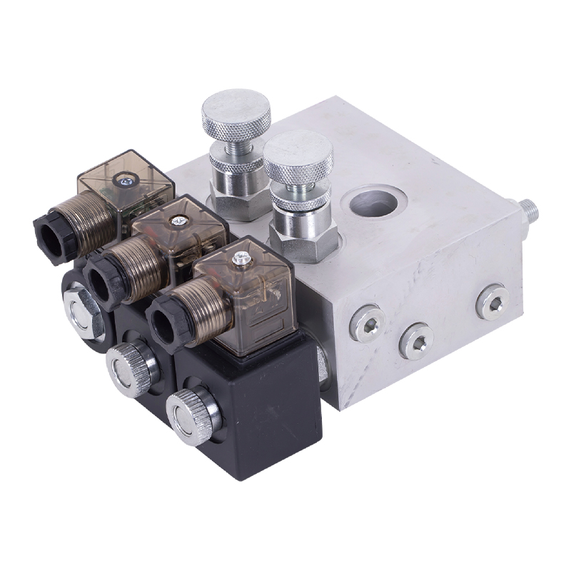
The power unit manifold block for lifting platform is the core integrated component of the hydraulic system, and plays a key role in coordinating vari...
See Details
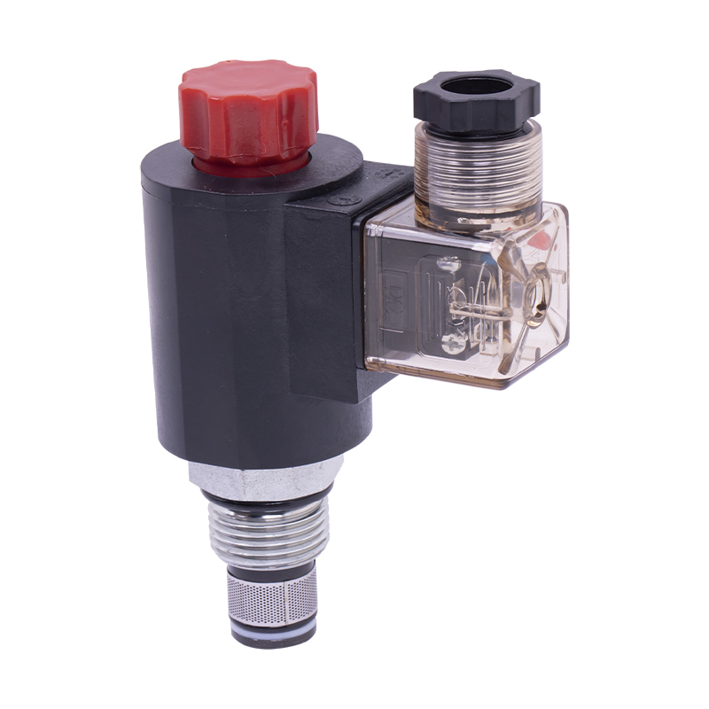
The relief valve is the core component for controlling pressure in the hydraulic system. It can maintain the stability of the system pressure and prev...
See Details
No. 12 Tongji Road, Simen Town, Yuyao City

+86-0574-62130352
+86-18905846028

+86-0574-62130353

Copyright© Ningbo Panic Hydraulic Technology Co., Ltd. All Rights Reserved. China Hydraulic Power Units Manufacturers
