
 English
 中文简体
中文简体 русский
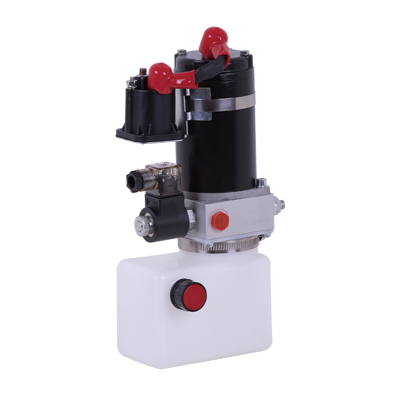
Power unit of forward moving stacker
Cat:DC series hydraulic power unit
This hydraulic power unit is specially designed for the forward stacker. It is integrated by a high-pressure gear pump, a DC Carbon brush or brushless...
See DetailsContent
Hydraulics work by using pressurized fluid — almost always oil — to transmit force and motion from one point to another. The underlying physics comes from Pascal's Law, which states that pressure applied to a confined fluid is transmitted equally in all directions throughout the fluid. In plain terms: push on one end of a sealed, fluid-filled system, and that force travels instantly and uniformly to wherever you direct it.
This makes hydraulics extraordinarily useful. A relatively small force applied over a large area can generate a massive output force at a smaller area — or the same force can move a load across a great distance with fine control. That combination of force multiplication, precision, and compactness is why hydraulic systems power excavators, aircraft landing gear, industrial presses, and hundreds of other machines that need to handle serious loads without enormous mechanical linkages.
At the heart of most modern hydraulic installations sits a Hydraulic Power Unit (HPU) — a self-contained assembly that generates, conditions, and delivers pressurized fluid to the actuators doing the actual work. Understanding how the whole system functions means understanding what happens at each stage, from the reservoir to the cylinder and back again.
Blaise Pascal formulated his principle in the 1650s, but its engineering applications took off during the Industrial Revolution. The law is straightforward: in a static fluid, any change in pressure at one point is transmitted without loss to every other point in the fluid. There is no mechanical leverage or gear reduction involved — the fluid itself carries the signal.
The practical result is a simple but powerful equation:
Force = Pressure × Area
If you apply 100 bar of pressure to a cylinder with a piston area of 50 cm², the output force is 50,000 N — roughly 5 tonnes. Scale the piston area up to 500 cm² at the same pressure and you get 500,000 N, or 50 tonnes. The pump generating that 100 bar does not change; only the cylinder size changes the output force. This scalability is impossible to match with purely mechanical systems of comparable compactness.
There is a trade-off, though. You cannot get something for nothing. A larger cylinder that exerts more force will move more slowly when supplied with the same flow rate. The relationship between flow, pressure, and velocity is fixed: increase force by enlarging the piston, and the piston moves proportionally slower for the same pump output. This is why hydraulic system designers must balance actuator sizing, pump capacity, and operating pressure for each application.
Liquids are essentially incompressible at practical working pressures. Hydraulic oil compressed to 350 bar changes volume by less than 2%. This near-incompressibility means hydraulic actuators respond almost instantaneously and hold their position under load without drift — a property pneumatic (air-based) systems cannot match, since air is compressible and acts more like a spring. For applications requiring precise load holding, such as a crane holding a load mid-air or a press maintaining clamping force, hydraulics are the default choice.
Mechanical linkages — gears, levers, lead screws — can theoretically do similar jobs, but they become enormous and heavy at high force levels. A 100-tonne hydraulic press fits in a workshop. The mechanical equivalent would fill a building.
Every hydraulic circuit — from a simple forklift mast to a complex ship steering system — shares a common set of core components. Each has a specific job, and failure of any one part typically brings the whole system down.
The reservoir stores the hydraulic fluid when it is not circulating in the system. It does more than just hold oil — a well-designed reservoir allows air bubbles to rise out of the fluid (de-aeration), lets heat dissipate, and allows contaminant particles to settle. Most reservoirs are sized to hold at least three to five times the pump's per-minute flow rate, giving the oil enough dwell time to condition itself before recirculation. In industrial Hydraulic Power Unit assemblies, the reservoir is typically a welded steel tank with inspection ports, drain plugs, level gauges, and a breather filter to allow air exchange without introducing contamination.
The pump converts mechanical energy (from an electric motor or engine) into fluid flow. It does not create pressure directly — it creates flow. Pressure only builds when that flow meets resistance in the circuit. The three main pump types used in hydraulic systems are:
Variable displacement piston pumps are particularly valuable because they adjust their output to match actual demand, dramatically reducing energy waste compared to fixed-displacement pumps that must bypass excess flow over a relief valve.
Valves direct, regulate, and limit fluid flow throughout the circuit. The main categories are:
Actuators convert fluid energy back into mechanical work. Hydraulic cylinders produce linear motion — a piston rod extending and retracting. Hydraulic motors produce rotary motion, much like a pump running in reverse. Cylinder forces commonly range from a few kilonewtons for small machinery up to tens of thousands of kilonewtons in heavy industrial presses and offshore lifting equipment.
Contamination is the number-one cause of hydraulic component failure — studies by component manufacturers consistently attribute 70–80% of hydraulic failures to fluid contamination. Filters remove solid particles; most industrial systems target ISO cleanliness levels of 16/14/11 or better. Heat exchangers (oil coolers) keep fluid temperature within the recommended operating range, typically 30–60 °C for mineral oil systems. Sustained overheating degrades oil viscosity, accelerates oxidation, and shortens seal life dramatically.
A Hydraulic Power Unit (HPU) — sometimes called a hydraulic power pack — is the packaged source of hydraulic energy in a system. It integrates the motor, pump, reservoir, relief valve, filter, and often a cooler into a single, skid-mounted assembly that can be installed and commissioned as one unit. The HPU is the "engine room" of the hydraulic circuit; everything downstream — cylinders, motors, valves — connects back to it.
In industrial settings, a Hydraulic Power Unit might serve a single machine or supply pressurized fluid to an entire production line through a central manifold. Offshore platforms commonly use HPUs rated at several hundred kilowatts to drive blowout preventers, riser tensioners, and pipe-handling equipment. In contrast, a compact HPU for a small metal-forming press might have a 5 kW motor and a 20-litre reservoir.
Selecting and specifying a Hydraulic Power Unit involves several interdependent choices:
A well-engineered Hydraulic Power Unit also includes instrumentation: pressure gauges, temperature sensors, level switches, and often a PLC or control panel to automate start/stop sequences, monitor fluid condition, and provide fault alarms. This instrumentation transforms a bare HPU into a manageable, maintainable system.
| Application | Typical Pressure (bar) | Flow Rate (L/min) | Motor Power (kW) | Reservoir (L) |
|---|---|---|---|---|
| Small press / clamping | 100–200 | 5–20 | 2–7.5 | 20–60 |
| Injection molding machine | 140–210 | 50–300 | 15–90 | 100–400 |
| Mobile crane / excavator | 250–350 | 100–400 | Engine-driven | 150–500 |
| Offshore / subsea HPU | 207–690 | 200–1,000+ | 75–500+ | 500–5,000+ |
Walking through a complete operating cycle reveals how each component contributes. Take a simple double-acting cylinder circuit — the kind used in a hydraulic press or a machine tool clamping unit:
That complete loop — from reservoir through pump, valve, cylinder, and back to reservoir — is a closed hydraulic circuit. Modern systems add refinements: pressure-compensated variable pumps that only produce flow when an actuator demands it, proportional valves that allow smooth speed ramping, and accumulators that store pressurized fluid to meet brief peak demands without oversizing the pump.
Accumulators deserve special mention because they are often misunderstood. A hydraulic accumulator stores energy in pressurized fluid (bladder or piston types are most common), using compressed nitrogen gas as the energy storage medium. They serve multiple functions: smoothing out pressure pulsations from gear pumps, supplying short bursts of high flow that would require a much larger pump, and maintaining system pressure when the pump is off (for example, holding a clamped workpiece while the machine cycles between operations). In emergency or fail-safe systems — aircraft landing gear, for instance — accumulators provide enough stored energy to complete a critical operation even if the main power source fails.

The fluid is not just a passive medium — it is a critical engineering material. A hydraulic fluid must simultaneously transmit power, lubricate moving parts inside the pump and valves, protect metal surfaces against corrosion, resist foaming, and remain stable across a wide temperature range. Getting the fluid selection wrong shortens component life and causes erratic system behavior.
Viscosity grade selection depends on operating temperature. A fluid that is too thin at operating temperature provides inadequate lubrication; one that is too viscous at startup causes cavitation (the formation of vapor bubbles in the pump intake) and excessive power loss. ISO VG 46 suits most temperate-climate industrial applications operating at 40–60 °C. Cold-climate or high-speed applications may require VG 32 or lower.
The terms "open-center" and "closed-center" describe what happens to pump flow when all actuators are at rest — it is one of the most fundamental design choices in a hydraulic system.
In an open-center system, the directional control valve allows pump flow to circulate continuously back to the tank through the valve body when the actuator is idle. Pressure is low (just enough to overcome return-line back-pressure). This is simple and reliable — it is the standard arrangement in most mobile equipment (tractors, forklifts, construction machinery) — but it wastes energy continuously circulating fluid even when no work is being done.
In a closed-center system, the valve blocks flow when the actuator is idle. This forces the system to use either a variable-displacement pump (which reduces its output to near-zero when flow is not needed) or an unloading valve that dumps flow to tank at very low pressure. Closed-center systems are more energy-efficient and are standard on modern industrial machinery and high-performance mobile equipment. The Hydraulic Power Unit in these systems often incorporates load-sensing controls, where the pump adjusts its displacement in real time to maintain only as much pressure as the actuator currently requires — typically 20–30 bar above load pressure.
| Feature | Open-Center | Closed-Center |
|---|---|---|
| Pump type | Fixed displacement | Variable displacement preferred |
| Idle energy consumption | High (flow circulates at low pressure) | Low (pump near standby) |
| Heat generation at idle | Moderate | Minimal |
| Complexity and cost | Lower | Higher |
| Typical application | Mobile equipment, agricultural machinery | Industrial presses, CNC, injection molding |
| Multi-actuator performance | Can cause interaction between circuits | Better isolation, more precise control |
Traditional hydraulics uses on/off solenoid valves — the actuator either moves at full speed or stops. Proportional hydraulics replaces those with proportional or servo valves that modulate flow continuously in proportion to an electrical command signal. The result is smooth, programmable, highly repeatable motion control that can be integrated with PLCs, CNC controllers, and computer-based automation systems.
Proportional valves operate on the same hydraulic principles — pressure, flow, Pascal's Law — but add a linear force motor or torque motor that positions the valve spool with precision. A 0–10 V or 4–20 mA signal from a controller commands the valve to any position between fully closed and fully open. Servo valves, the more precise (and expensive) variant, can achieve positioning accuracy under 0.01 mm in closed-loop cylinder applications.
Modern Hydraulic Power Unit designs increasingly incorporate electrohydraulic controls at the HPU level: variable-displacement pumps with electronic pressure or flow control, servo-driven pump motors (where a variable-speed electric drive replaces the traditional fixed-speed motor + variable-pump arrangement), and integrated condition monitoring. A servo-drive HPU can reduce energy consumption by 30–60% compared to a conventional fixed-pump HPU in applications with highly variable duty cycles, such as injection molding or die casting.
Hydraulic systems appear wherever high force, power density, or precise load control is required. The following categories illustrate why hydraulics remain dominant despite the rise of electromechanical alternatives:
Excavators, bulldozers, and hydraulic rock breakers rely on hydraulics because no other technology delivers the same combination of high force, infinite speed variation, and rugged reliability in a mobile, engine-powered package. A 20-tonne excavator typically runs two or three variable-displacement piston pumps driven by its diesel engine, collectively supplying several hundred liters per minute to swing motors, travel motors, and boom/arm/bucket cylinders — all simultaneously and independently controllable.
Sheet metal stamping, forging, and deep-drawing presses use hydraulic cylinders because the force can be maintained constant throughout the stroke — unlike mechanical eccentric or crank presses, which have a sinusoidal force curve. A hydraulic press can hold full tonnage at any point in its stroke, which is essential for forming thick plate or for precision coining operations. Industrial hydraulic presses routinely produce forces of 1,000 to 10,000 tonnes from a compact Hydraulic Power Unit arrangement.
Aircraft flight control surfaces, landing gear, and thrust reversers are hydraulically actuated on most large commercial jets. The Boeing 747 runs three independent hydraulic systems, each at 207 bar (3,000 psi), with a combined total reservoir capacity of around 600 liters. Hydraulics are preferred here because they are highly power-dense (small and light relative to force output), inherently stiff (incompressible fluid means precise surface position), and well-understood in terms of failure modes — critical in a safety-certified environment.
Ship steering gear, deck cranes, hatch covers, offshore blowout preventers, and subsea wellhead control systems all use hydraulics. Offshore Hydraulic Power Units are engineered to operate in explosive atmospheres (ATEX-rated) and often include redundant pumps, emergency backup accumulators, and continuous fluid monitoring. Subsea HPUs operate at depths where ambient pressure exceeds 300 bar — a design challenge that requires pressure-compensated reservoirs and specially rated component seals.
Injection molding machines are one of the largest single markets for hydraulic systems. The injection, clamping, and ejection functions each demand different pressure and flow profiles within a single short cycle. Servo-hydraulic HPUs have become the standard in this industry, offering the force capability of hydraulics with the energy efficiency and repeatability of electric drives. Cycle times under 10 seconds are common for high-volume parts, meaning the HPU may complete hundreds of thousands of cycles per year — durability and reliability are paramount.
Each power transmission technology has genuine strengths and real weaknesses. The choice between hydraulics, pneumatics, and electromechanical (ball screw, linear motor, rack and pinion) systems comes down to force level, speed, precision, environment, and total cost of ownership.
| Parameter | Hydraulic | Pneumatic | Electromechanical |
|---|---|---|---|
| Force output | Very high | Low to moderate | Low to high (depends on design) |
| Position accuracy | High (servo), moderate (on/off) | Low | Very high |
| Energy efficiency | Moderate–high (servo HPU) | Low (compression losses ~90%) | High |
| Load holding at rest | Excellent (check valves) | Poor (air compressible) | Good (brake required) |
| Fire/explosion risk | Moderate (mineral oil flammable) | None | Low |
| Maintenance complexity | Moderate | Low | Low–moderate |
| Power density | Highest | Moderate | Moderate |
Electromechanical linear actuators (especially those driven by servo motors through ball screws) have made significant inroads into applications once dominated by hydraulics — particularly where cleanliness, energy efficiency, and precise positioning are priorities, such as pharmaceutical manufacturing or semiconductor equipment. However, at force levels above roughly 50–100 kN, the physical size and cost of electromechanical alternatives become prohibitive, and hydraulics remain unmatched.
Hydraulic systems give clear symptoms when something goes wrong. Knowing what each symptom points to cuts diagnostic time dramatically.
When a cylinder extends slowly or cannot reach full force, the usual suspects are: worn pump (internal bypass reducing volumetric efficiency), a relief valve that has drifted low or is stuck open, a leaking counterbalance or load-holding valve, or internal cylinder bypass past worn seals. Checking system pressure with a gauge at the pump outlet reveals immediately whether the pump is generating rated pressure. If pump pressure is normal but the actuator is slow, the fault is downstream — likely a valve or the cylinder itself.
Hydraulic oil operating above 60–70 °C degrades rapidly, loses viscosity, and attacks seals. Overheating typically indicates: an undersized or blocked oil cooler, a relief valve that is continuously cracking (dumping energy as heat), a pump bypassing internally due to wear, or a circuit that has been redesigned to run at higher duty than the original thermal design allowed. Infrared thermometry on the return line, cooler, and reservoir pinpoints where heat is being generated.
A whining or screaming pump usually means cavitation — the pump is not getting adequate fluid at its inlet. Causes include a clogged suction strainer, a collapsed suction hose, a fluid level too low, or a fluid with too high a viscosity for the operating temperature. A knocking or chattering noise is more often aeration — air entering the fluid through a loose suction fitting or a leaking shaft seal on the pump, causing air bubbles to collapse violently inside the pump. Both conditions damage pump internals rapidly; cavitation and aeration are leading causes of premature pump failure.
Visible oil leaks are the most obvious sign of seal failure, cracked fittings, or hose deterioration. Beyond the safety and environmental hazards, external leaks indicate the fluid cleanliness level is being compromised as makeup oil is added. Any system losing more than 1–2% of its oil volume per month should be investigated promptly. Hoses typically have a service life of 5–7 years regardless of visual condition, and scheduled replacement is good practice in high-cycle industrial applications.
The overwhelming majority of hydraulic failures are preventable. A disciplined maintenance program focused on fluid cleanliness, temperature, and early fault detection extends component life by a factor of two to five compared to reactive (fix-it-when-it-breaks) approaches.
A Hydraulic Power Unit with proper preventive maintenance should deliver 20,000–40,000 hours of service life from its pump and motor — equivalent to 10–20 years in a two-shift industrial operation. Neglected systems rarely reach half that.
Most hydraulic systems use mineral-based hydraulic oil, commonly ISO VG 46 or VG 68. Fire-resistant fluids, biodegradable oils, and water-glycol blends are used where environmental regulations or fire risk require them. The fluid must be compatible with the seals, hoses, and metals in the system — always consult the equipment manufacturer before switching fluid types.
A hydraulic pump is driven mechanically (by an electric motor or engine) and converts that mechanical energy into fluid flow and pressure. A hydraulic motor does the opposite — it receives pressurized fluid and converts it into rotary mechanical output. Many pump designs can theoretically be run as motors, though in practice pumps and motors are optimized differently for their respective roles.
Industrial hydraulic systems most commonly operate between 100 and 350 bar (1,450–5,000 psi). Mobile equipment (excavators, cranes) typically runs at 250–350 bar. Aircraft hydraulics typically use 207 bar (3,000 psi), with some newer aircraft moving to 350 bar (5,000 psi) to save weight through smaller components. Ultra-high-pressure systems for special applications can exceed 1,000 bar.
Hydraulic systems generate heat whenever fluid is throttled across a valve or bypassed over a relief valve — all of that pressure drop converts to heat. Overheating happens when heat generation exceeds the system's cooling capacity. Common causes include an undersized cooler, a blocked cooler or heat exchanger, a relief valve that is continuously opening, a pump with poor volumetric efficiency, or a duty cycle more demanding than the original design specified.
A Hydraulic Power Unit typically comprises a reservoir, an electric motor (or combustion engine for mobile units), one or more hydraulic pumps, a system relief valve, a pressure filter, a return-line filter, a breather filter, fluid level and temperature gauges, and often an oil cooler. More sophisticated HPUs include directional valves, pressure-reducing valves, flow controls, accumulators, and programmable control panels — everything needed to generate, condition, and deliver hydraulic power to the actuators in the machine or system it serves.
Not in normal operation — the pump is the source of all flow and, indirectly, all pressure. However, a hydraulic accumulator can supply short bursts of flow to an actuator after the pump stops. Emergency hydraulic systems on aircraft and some industrial machinery rely on accumulators to complete a critical operation (retracting landing gear, releasing a brake) even after total power loss. The accumulator stores energy like a pressurized battery but has limited capacity and cannot sustain continuous operation.

This hydraulic power unit is specially designed for the forward stacker. It is integrated by a high-pressure gear pump, a DC Carbon brush or brushless...
See Details
This boarding axle power unit is specially designed for fixed boarding ramps and integrates a high-pressure gear pump, an AC motor center valve block,...
See Details
This hydraulic power unit is designed for telescopic belt conveyors. It integrates a high-pressure gear pump, AC motor, center valve block, cartridge ...
See Details
This hydraulic power unit is specially designed for the clamping cylinder of the machine, too. It is integrated by a high-pressure gear pump.AC motor,...
See Details
This hydraulic power unit is specially designed for the storage flushing door and is integrated with a high-pressure gear pump, AC motor, central valv...
See Details
This hydraulic power unit is specially designed for an anti-terrorism hydraulic roadblock machine. It is integrated by a high-pressure gear pump, an A...
See Details
This hydraulic power unit is specially designed for hydraulic cargo elevators and is integrated with a high-pressure vane pump, AC Oil immersion motor...
See Details
This hydraulic power unit is specially designed for the three-dimensional parking garage and is integrated by a high-pressure vanepump, an AC oil imme...
See Details
The power unit check valve (also called non-return valve) is a key component for controlling the one-way flow of fluids. It can prevent hydraulic oil,...
See Details
The relief valve is the core component for controlling pressure in the hydraulic system. It can maintain the stability of the system pressure and prev...
See Details
No. 12 Tongji Road, Simen Town, Yuyao City

+86-0574-62130352
+86-18905846028

+86-0574-62130353

Copyright© Ningbo Panic Hydraulic Technology Co., Ltd. All Rights Reserved. China Hydraulic Power Units Manufacturers
