
 English
 中文简体
中文简体 русский
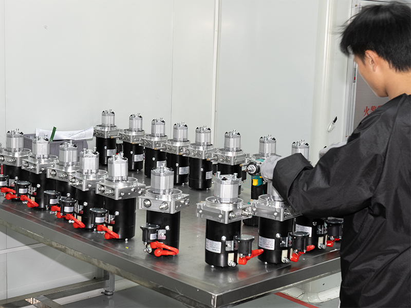
Mini Pallet Truck Hydraulic Power Unit
Cat:DC series hydraulic power unit
This hydraulic power unit is specially designed for all electric pallet truck.It consists of high voltage gear pump,permanent magnet DC motor and cent...
See DetailsContent
Hydraulic systems transmit, multiply, and precisely control mechanical force by transferring pressure through an enclosed fluid. The core function is straightforward: a small force applied to a small piston generates the same pressure as a large force applied to a large piston, because pressure distributes equally throughout a confined liquid (Pascal's Law). This makes hydraulic technology one of the most force-efficient mechanical solutions ever engineered — capable of moving tens of thousands of kilograms with equipment that an operator controls with a single hand. The Hydraulic Power Unit (HPU) sits at the center of this process, acting as the pressurized fluid source that every actuator in the system depends on.
Pascal's Law states that pressure applied to an enclosed fluid is transmitted undiminished in all directions. The mathematical consequence is that force output scales directly with piston area. If an operator pushes with 100 N on a piston with a 1 cm² surface, the resulting pressure of 100 N/cm² propagates throughout the fluid. When that pressure reaches an output cylinder with a 50 cm² face, it delivers 5,000 N — a 50:1 force multiplication without any additional energy input beyond what Pascal's Law demands.
This is not magic or a free energy source. The trade-off is distance: the output piston moves only 1/50th of the distance the input piston travels. Energy is conserved. What hydraulics do exceptionally well is reshape force and displacement into the ratio that a specific application requires — something mechanical gears accomplish but with far more friction loss and structural complexity.
In a real industrial system, the Hydraulic Power Unit generates this pressure continuously and on demand. A typical HPU combines a reservoir (often 50–500 liters), a motor-driven pump, pressure relief valves, filtration, and cooling circuits. The pump converts rotary mechanical energy into fluid pressure, commonly achieving operating pressures between 140 bar and 350 bar depending on the application. That pressure is the stored mechanical potential that actuators convert back into linear or rotary force wherever it is needed.
A common point of confusion is the relationship between pressure and flow. Pressure (measured in bar or PSI) determines the force a cylinder can exert. Flow rate (measured in liters per minute or GPM) determines how fast the cylinder moves. The Hydraulic Power Unit must supply both in the correct combination:
The formula F = P × A (Force equals Pressure multiplied by Cylinder Area) governs every actuator in the circuit. Engineers use this equation to size cylinders, select pump ratings, and set relief valve thresholds during the design phase.
The Hydraulic Power Unit is not simply a pump bolted to a tank. Its role in managing force throughout a system is active and continuous. An HPU regulates three force-related parameters simultaneously: the maximum available pressure (set by the main relief valve), the working pressure delivered to each circuit branch (set by individual pressure-reducing valves), and the rate at which force can be applied (governed by flow control valves).
Every Hydraulic Power Unit incorporates at least one relief valve set to the system's maximum permissible pressure. When an actuator stalls against an immovable load, the pump continues to deliver flow. Without a relief valve, pressure would climb until something failed mechanically. The relief valve diverts excess flow back to the reservoir, capping force at a safe level. In a 200-bar system operating a 80 cm² bore cylinder, the theoretical maximum force output is 160,000 N (approximately 16.3 metric tons) — and that ceiling is maintained by the HPU's relief setting, not by operator restraint.
Modern hydraulic power units increasingly integrate proportional or servo valves that allow infinitely variable force output between zero and the system maximum. Unlike on/off directional control valves, proportional valves respond to an electrical signal (typically 0–10 V or 4–20 mA) and position their spool in direct proportion to that signal. The result is that a press can apply 5,000 N during one phase of a cycle and ramp smoothly to 80,000 N during the pressing phase — all controlled by the HPU's electronic controller without mechanical adjustments.
A load-sensing Hydraulic Power Unit continuously measures the pressure demand at the actuator and adjusts pump output to match. Rather than generating maximum pressure at all times and dumping the excess over a relief valve, the load-sensing HPU generates only the pressure the load actually requires plus a small margin (typically 20–30 bar above load pressure). This approach reduces energy consumption by 30–50% compared to fixed-displacement systems in applications with variable loads — a significant advantage in mobile equipment, injection molding machines, and automated press lines.
Hydraulic systems handle several distinct force categories, and understanding each explains why the technology appears in such varied applications — from aerospace landing gear to agricultural harvesting equipment.
| Force Type | Description | Typical Application | Typical Force Range |
|---|---|---|---|
| Linear compressive | Pushing directly against a surface | Hydraulic press, metal stamping | 10 kN – 100,000 kN |
| Linear tensile | Pulling or stretching under tension | Pipe pulling, bolt tensioning | 5 kN – 50,000 kN |
| Rotary torque | Twisting force via hydraulic motor | Excavator slew ring, winch | 100 Nm – 500,000 Nm |
| Clamping | Holding a workpiece securely | CNC machining fixtures, die casting | 1 kN – 5,000 kN |
| Braking / holding | Resisting movement under load | Cranes, elevator counterbalance | Variable, often equal to load weight |
Each force category requires a specifically configured Hydraulic Power Unit and circuit. A bolting application demanding tensile forces needs a high-pressure HPU (often 700–1,000 bar for hydraulic bolt tensioners) with low flow rates and precision pressure control. A large winch application prioritizes continuous high-torque output from a hydraulic motor fed by a high-flow HPU. The same physical principles apply but the component selection differs substantially.
The hydraulic cylinder is the most common actuator for converting fluid pressure into linear force. It consists of a steel barrel, a piston, and a rod. Pressurized oil from the Hydraulic Power Unit enters one side of the piston, creating a net force that pushes the piston and rod in the opposite direction. The force produced follows F = P × A directly.
Double-acting cylinders — those that receive pressure on both sides — produce different forces in extension and retraction. On extension, the full bore area (e.g., 100 cm²) is exposed to pressure. On retraction, the rod occupies part of the piston face, leaving a smaller annular area (e.g., 65 cm² if the rod reduces the effective area by 35%). At 200 bar, extension force is 200,000 N; retraction force is only 130,000 N from the same pressure source. Circuit designers must account for this asymmetry when specifying both the HPU output and the mechanical structure surrounding the cylinder.
When a cylinder holds a suspended load — a raised crane boom, a tilted dump truck body, a lifted press platen — gravity applies continuous force that the hydraulic circuit must resist. Counterbalance valves are piloted check valves set slightly above the load-induced pressure. They prevent the cylinder from moving unless the HPU actively commands motion. Without them, a hose failure or valve malfunction would allow loads to drop uncontrolled. Counterbalance valves are therefore a critical force-safety device, not an optional refinement.
The gap between textbook hydraulics and actual deployed systems often comes down to how force is managed under varying conditions. Several industries demonstrate the breadth of what hydraulic force manipulation achieves in practice.
A large hydraulic press used for deep drawing sheet metal might apply 5,000 kN of compressive force — roughly 500 metric tons. The Hydraulic Power Unit supplying such a press typically runs at 250–350 bar and incorporates hydraulic accumulators to handle peak flow demands during the forming stroke without oversizing the drive motor. Accumulators store pressurized fluid between strokes and release it rapidly when the press demands maximum force over a short duration. This allows the HPU motor to be sized for average power rather than peak power, often reducing motor size by 40–60% compared to a system without accumulators.
Subsea blowout preventers (BOPs) on oil and gas wells operate at depths where no mechanical access is possible. Their Hydraulic Power Unit — often called a Subsea Control Module in this context — must close rams that seal a well bore against pressures exceeding 690 bar (10,000 PSI). The rams themselves require actuation forces in the tens of millions of Newtons. Redundancy is non-negotiable: every subsea HPU incorporates multiple independent pressure accumulators with enough stored energy to operate the BOP at least twice without any surface power supply, as mandated by international well control regulations.
A 50-tonne excavator uses its engine-driven hydraulic pump as a mobile Hydraulic Power Unit feeding the boom, arm, bucket, and swing circuits simultaneously. Typical working pressures sit between 320 and 380 bar. The bucket cylinder alone can generate 350–500 kN of breakout force, allowing the machine to cut through compacted rock-hard soils. Modern excavators use electronic load-sensing controls that monitor each circuit's pressure demand and adjust pump displacement accordingly, keeping the engine operating near its efficiency peak rather than lugging at full throttle against an oversized load.
Commercial aircraft use hydraulic systems operating at 207 bar (3,000 PSI) — with some newer platforms moving to 345 bar (5,000 PSI) — to move flight control surfaces against aerodynamic loads that can reach hundreds of kilonewtons at high speed. The aircraft's engine-driven pumps serve as onboard Hydraulic Power Units, supplemented by electric motor pumps and ram air turbines for emergency backup. Force here must be not just large but precisely proportional to pilot input, which is why electrohydrostatic actuators (EHAs) — self-contained hydraulic power units integrated into each actuator — are increasingly used on fly-by-wire aircraft.
No hydraulic system is 100% efficient. Force and energy losses occur at multiple points, and a well-engineered Hydraulic Power Unit addresses each source systematically.
As oil flows through pipes, hoses, and valve passages, viscous friction consumes pressure. This pressure drop means the actuator receives less pressure than the HPU generates. The Hagen-Poiseuille relationship shows that pressure drop increases with the fourth power of velocity in laminar flow — meaning that doubling pipe diameter (and thus reducing flow velocity) drops resistance by a factor of 16. Well-sized hydraulic lines limit velocity to 2–4 m/s in pressure lines and 1–2 m/s in return lines to keep friction losses below 2–3% of system pressure in normal operation.
All hydraulic cylinders and valves have internal leakage — oil that bypasses seals and spool clearances without doing useful work. In a cylinder with worn seals, internal leakage allows the piston to drift under load, and the HPU must continuously compensate by supplying additional flow just to maintain position. Internal leakage in a healthy cylinder is typically 1–5 mL/min at rated pressure; worn seals can increase this to hundreds of mL/min, causing both force loss and HPU overheating as the diverted oil converts kinetic energy into heat without moving any load.
Hydraulic oil viscosity decreases as temperature rises. At the correct operating temperature (typically 40–60°C), the oil provides adequate lubrication and controllable leakage. Above 80°C, viscosity drops sharply, leakage increases, seal degradation accelerates, and oxidation begins breaking down the oil's chemistry. A Hydraulic Power Unit's heat exchanger maintains fluid temperature within this acceptable band. Industrial HPUs are typically sized to reject 25–35% of input power as heat in continuous operation — a reminder that a significant fraction of the mechanical energy invested in pressurizing the fluid never reaches the actuator as useful force.
Understanding what hydraulic systems do with force becomes clearer when compared against pneumatic and electromechanical alternatives.
The conclusion from this comparison is that hydraulic force multiplication remains unmatched in power density — the ratio of force output to system volume and weight. A hydraulic cylinder generating 1,000 kN might weigh 80 kg and occupy 0.04 m³. An equivalent electromechanical actuator would weigh several times more and occupy considerably more space.
Specifying an HPU for a known force requirement follows a logical sequence. Each step builds on the previous one, and errors early in the calculation cascade into oversized or undersized equipment.
This structured approach ensures the Hydraulic Power Unit delivers exactly the force the application needs — no more and no less — at the efficiency and reliability level the operating environment demands. Oversized HPUs waste energy and capital; undersized units run hot, cycle relief valves constantly, and fail prematurely.
Because pressure is directly proportional to force in a hydraulic circuit, monitoring system pressure provides real-time force data at low cost. A pressure transducer mounted near a cylinder's cap port reads the pressure acting on the full bore area; multiplying by that area gives the current applied force. Modern HPU control panels integrate this measurement continuously, displaying force in engineering units and triggering alarms or shutdowns if force limits are exceeded.
For applications requiring tighter force accuracy — load testing, material testing machines, structural testing rigs — dedicated load cells in series with the cylinder rod provide direct force measurement independent of friction losses in cylinder seals or guide bearings. The HPU then receives closed-loop feedback and adjusts pressure output to hold the commanded force within ±0.5% or better, depending on valve technology and controller tuning.
Condition monitoring systems on industrial HPUs also track force indirectly through vibration signatures, temperature trends, and efficiency calculations. A pump that produces 250 bar but consumes 20% more power than its baseline suggests internal wear that is reducing volumetric efficiency — meaning more and more flow is bypassing internally rather than doing work. Catching this trend early prevents the exponential degradation that leads to unplanned shutdowns.
The same force multiplication that makes hydraulics useful also makes them dangerous when force is released uncontrollably. A hose failure on a 350-bar system releases stored energy at a rate that can inject fluid through skin at distances exceeding 15 cm — causing injuries that appear minor externally but require immediate surgical intervention to prevent gangrene and amputation from deep tissue contamination.
Beyond injection hazards, uncontrolled force release from a cylinder supporting a heavy load creates catastrophic mechanical hazards. Every Hydraulic Power Unit serving a load-holding application must incorporate:
Force safety in hydraulics is a design requirement, not a retrofit option. Systems engineered from the first principles of controlled force transmission — with the Hydraulic Power Unit as the regulated source and properly specified valves, actuators, and lines as the controlled pathway — operate safely for decades. Systems that treat safety as secondary to initial cost routinely fail in ways that injure operators and destroy equipment.

This hydraulic power unit is specially designed for all electric pallet truck.It consists of high voltage gear pump,permanent magnet DC motor and cent...
See Details
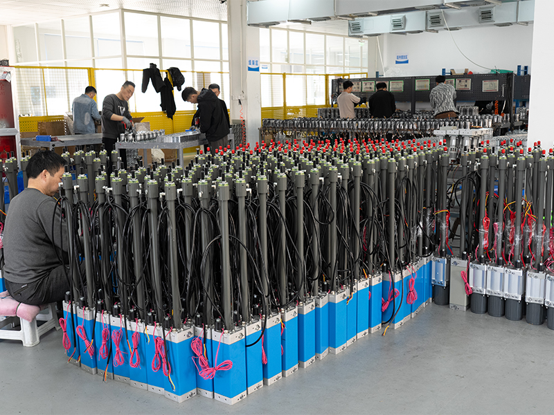
This hydraulic power unit is specially designed for the forward stacker. It is integrated by a high-pressure gear pump, a DC Carbon brush or brushless...
See Details
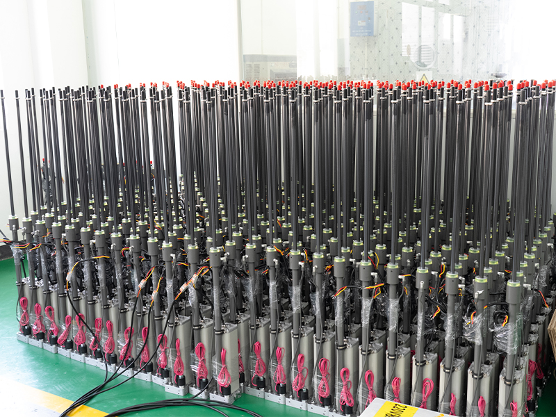
This hydraulic power unit is specially designed for a mobile hydraulic lifting table, which is integrated with a high-pressure gear pump. permanent ma...
See Details
This hydraulic power unit is specially designed for hot-melt butt welding machine and is integrated by high-pressure gear pump, AC motor central valve...
See Details
This hydraulic power unit is specially designed for the storage flushing door and is integrated with a high-pressure gear pump, AC motor, central valv...
See Details
This hydraulic power unit is specially designed for an anti-terrorism hydraulic roadblock machine. It is integrated by a high-pressure gear pump, an A...
See Details
This hydraulic power unit is specially designed for the three-dimensional parking garage and is integrated by a high-pressure vanepump, an AC oil imme...
See Details
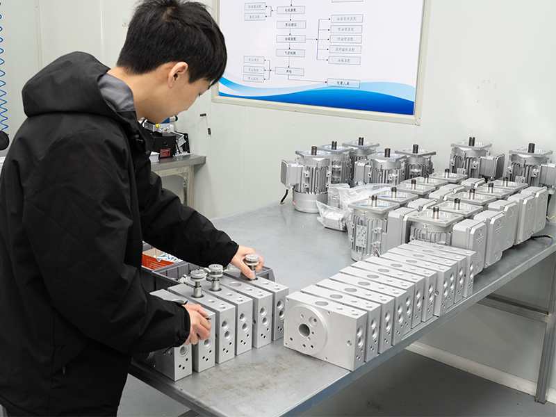
The modular hydraulic valve block uses modular integrated design to accurately combine multiple hydraulic valves, greatly simplifying the system pipel...
See Details
The multi-connection hydraulic integrated valve block is an efficient integrated component of the hydraulic system, including two-connection, three-co...
See Details
The power unit check valve (also called non-return valve) is a key component for controlling the one-way flow of fluids. It can prevent hydraulic oil,...
See Details
No. 12 Tongji Road, Simen Town, Yuyao City

+86-0574-62130352
+86-18905846028

+86-0574-62130353

Copyright© Ningbo Panic Hydraulic Technology Co., Ltd. All Rights Reserved. China Hydraulic Power Units Manufacturers
