
 English
 中文简体
中文简体 русский
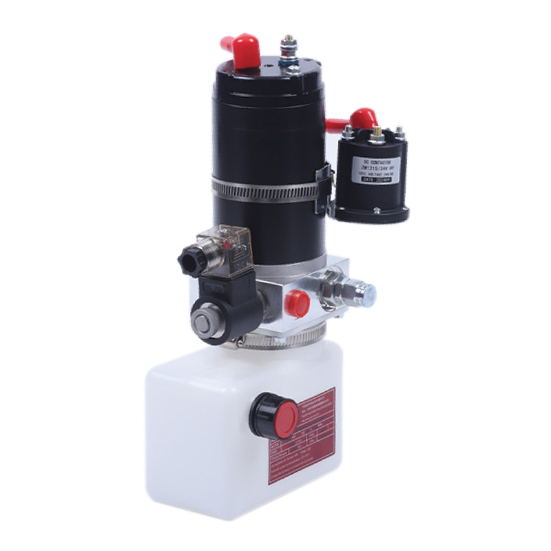
Portable stacker power unit
Cat:DC series hydraulic power unit
This portable stacker hydraulic power unit is designed for portable stackers and integrates a high-pressure gear pump, a permanent magnet DC motor, a ...
See DetailsContent
Hydraulic pressure works by transmitting force through an enclosed, incompressible fluid — almost always oil — from one point to another. When a pump pushes fluid into a sealed system, pressure builds and acts equally in all directions on every surface it contacts. That pressure is then directed to a cylinder or motor, where it converts back into mechanical force or rotation. The result is an ability to move enormous loads with relatively compact equipment.
The underlying principle is Pascal's Law: pressure applied to a confined fluid is transmitted undiminished throughout that fluid. Stated mathematically, P = F/A, where P is pressure in pascals or psi, F is applied force in newtons or pounds, and A is the area in square meters or square inches. This relationship means that by changing the area of a cylinder, a system can multiply or reduce force dramatically — the same reason a 70 kg technician pressing a small pump handle can lift a 20-tonne press.
Every industrial hydraulic system — from a factory press to a construction excavator — relies on this same chain of events: a Hydraulic Power Unit (HPU) generates pressurized fluid, control valves direct it, and actuators convert it into work. Understanding each step reveals why hydraulics remains the preferred choice wherever high force density and precise control both matter.
Blaise Pascal formulated his law of fluid mechanics in 1653, but its engineering implications only became fully exploitable in the 19th and 20th centuries with the development of precision seals and high-strength steel tubing. The core idea is deceptively simple: liquids do not compress meaningfully under normal working pressures, so any force you introduce at one point propagates instantly and uniformly to every other point in the system.
Consider a basic two-cylinder example. If you apply 100 N of force to a piston with an area of 1 cm², the resulting pressure is 100 N/cm² = 1 MPa. Connect that small cylinder via a fluid-filled pipe to a larger cylinder with an area of 100 cm², and the same 1 MPa pressure acts on the entire 100 cm² face — producing an output force of 10,000 N. The system has multiplied force by a factor of 100 without any additional energy input. The trade-off is displacement: the small piston must travel 100 mm to move the large piston just 1 mm. Energy is conserved; force is amplified at the expense of speed and stroke.
This force-multiplication principle is why hydraulics appears wherever weight and compactness matter together. A pneumatic cylinder working at 8 bar (0.8 MPa) produces modest force because air pressure is limited. A hydraulic cylinder working at 250 bar (25 MPa) — a typical industrial operating pressure — delivers force roughly 30 times greater from the same bore size.
A complete hydraulic circuit is made up of several interdependent components. Each one plays a specific role, and weakness in any link — a worn seal, an undersized valve, a contaminated reservoir — degrades performance across the entire system.
The reservoir stores the working fluid and allows air bubbles and heat to dissipate before fluid recirculates. Industrial reservoirs are sized at roughly 2–3 times the pump's per-minute flow rate to provide adequate dwell time. A 50 L/min pump typically pairs with a 100–150 L reservoir. The reservoir also houses breather filters, a level sight glass, drain plugs, and often a temperature gauge — making it the health-monitoring hub of the circuit.
The pump does not create pressure directly; it creates flow. Pressure only develops when that flow meets resistance — a load, a valve, or a blocked path. Three pump types dominate industrial and mobile applications:
Variable-displacement piston pumps are particularly valuable in a Hydraulic Power Unit because they automatically reduce output when demand drops, slashing energy consumption and heat generation during partial-load cycles.
Valves are the nervous system of a hydraulic circuit. Directional control valves (DCVs) route flow to whichever actuator needs it. Pressure relief valves (PRVs) cap maximum system pressure — typically set 10–15% above peak operating pressure — to protect components from overload. Flow control valves meter the rate at which fluid enters or exits an actuator, directly controlling actuator speed. Check valves prevent backflow. Proportional and servo valves add fine electronic control, enabling closed-loop position or force regulation with positioning repeatability better than 0.01 mm in precision applications.
Actuators convert hydraulic energy back into mechanical work. Linear cylinders produce push or pull force; rotary hydraulic motors produce torque and rotation. Cylinder output force is calculated as F = P × A, so a 100 mm bore cylinder (area ≈ 78.5 cm²) operating at 200 bar (20 MPa) develops approximately 157,000 N — or 16 tonnes — of push force. That level of force from an electric servo motor of equivalent size would require a motor several times larger and heavier.
Contamination is the single largest cause of hydraulic component failure — responsible for an estimated 70–80% of all premature failures according to fluid power industry data. Return-line filters, suction strainers, and off-line kidney-loop filtration systems maintain cleanliness levels. Servo valve applications typically require ISO cleanliness class 16/14/11 or better, which means fewer than 1,300 particles larger than 4 µm per millilitre of fluid.
A Hydraulic Power Unit (HPU) — sometimes called a hydraulic power pack — is a self-contained assembly that integrates the reservoir, pump, prime mover (electric motor or combustion engine), pressure relief valve, filter, heat exchanger, and instrumentation into a single packaged unit. Rather than scattering these components across a machine frame, the HPU consolidates them into one engineered system that can be installed, maintained, and swapped out as a unit.
HPUs range from compact bench-top units producing 1–5 kW and operating at 70–150 bar to multi-megawatt industrial power units driving steel mill presses at pressures above 400 bar. A mid-range industrial Hydraulic Power Unit might pair a 30 kW electric motor with a 45 cc/rev axial piston pump, a 200 L reservoir, a water-cooled heat exchanger maintaining oil temperature at 45–55°C, and a 10 µm return-line filter — all mounted on a powder-coated steel base frame with integrated drip tray.
| Parameter | Typical Range | Why It Matters |
|---|---|---|
| Operating pressure | 70–700 bar | Determines maximum force output from actuators |
| Flow rate | 2–2,000 L/min | Governs actuator speed and cycle time |
| Motor power | 0.5–2,000 kW | Must match worst-case demand with margin |
| Reservoir volume | 5–10,000 L | Affects thermal stability and contamination control |
| Filtration rating | 3–25 µm | Protects valves, pump internals, and seals |
| Fluid temperature range | 30–65°C operating | Viscosity shifts with temperature, affecting efficiency |
HPU design also involves choices about redundancy. Critical processes — offshore platform control systems, steel mill rolling mills, aircraft ground support equipment — often use duplex Hydraulic Power Units with two pumps, where one operates and one stands by on automatic switchover. Downtime costs in those environments can exceed tens of thousands of dollars per hour, making redundancy economically rational even at significant capital cost.
Understanding the dynamic behaviour of pressure — not just the static formula — is essential for anyone designing or troubleshooting hydraulic systems. Pressure does not simply switch on. It rises, peaks, oscillates, and stabilizes in patterns that depend on pump type, valve response speed, line lengths, and fluid compressibility.
When a directional valve closes rapidly, the momentum of moving fluid has nowhere to go. The result is a pressure transient — a spike — that can reach 2–5 times the steady-state operating pressure in under 5 milliseconds. A system running at 200 bar can see transient peaks above 500 bar. These spikes fatigue hose fittings, crack manifold blocks, and destroy seals over repeated cycles. Designers counter them with pressure accumulators (which absorb the energy spike), slow-closing valves, or pilot-operated check valves with controlled opening rates.
Every hydraulic system must have a pressure relief valve (PRV) set below the weakest component's rated pressure. If an actuator reaches end-of-stroke with the pump still running, pressure would otherwise climb until something ruptures. The PRV opens when pressure exceeds its set point, bypassing flow back to tank. This is not a normal operating condition — a PRV that opens continuously is wasting energy as heat and signalling a system design or operational problem. The correct design routes the PRV flow only during genuine overload events, keeping it closed the vast majority of the time.
A hydraulic accumulator is a pressure vessel containing a pre-charged gas (almost always nitrogen) separated from the hydraulic fluid by a bladder, piston, or diaphragm. When system pressure exceeds the gas pre-charge, fluid compresses the gas and stores energy. When pressure drops — during a demand spike or pump failure — the gas expands and pushes fluid back into the circuit. Accumulators serve three main functions: energy storage for peak demand supplementation, emergency pressure supply for safe shutdown actuation, and pulsation dampening. A 20 L bladder accumulator pre-charged to 150 bar can deliver a brief flow supplement of 8–12 L at system pressure — enough to complete a safety-critical valve movement even after pump loss.

The fluid in a hydraulic system is not simply a force-transmission medium. It simultaneously lubricates every moving surface inside the pump, valves, and actuators, carries heat away from hot spots, protects metal surfaces from corrosion, and suspends contamination particles until they reach a filter. Choosing the wrong fluid or allowing it to degrade destroys components faster than almost any other single factor.
Viscosity is the most critical fluid property. Most industrial Hydraulic Power Units specify ISO VG 46 mineral oil — a viscosity grade of 46 centistokes (cSt) at 40°C. As temperature rises to 80°C, viscosity drops to roughly 12 cSt; at 20°C it may be 100 cSt or higher. Operating below minimum viscosity causes metal-to-metal contact and rapid wear; operating above maximum viscosity causes cavitation, sluggish response, and high pump inlet vacuum. Most systems target 25–54 cSt at the pump inlet for optimal balance.
Particle counters, moisture sensors, and viscosity analysers are now routinely installed on larger Hydraulic Power Units as part of condition monitoring programmes. Online particle counters sampling return-line fluid can detect a deteriorating pump bearing weeks before it fails catastrophically — translating into planned maintenance windows rather than emergency shutdowns. Water content above 0.05% in mineral oil emulsifies the fluid, destroys the oil film on bearing surfaces, and promotes rust. Even 500 ppm (0.05%) of water has been shown to reduce roller bearing fatigue life by up to 75%.
Not all hydraulic systems are configured the same way. The circuit architecture determines how efficiently power is used, how responsive the system feels, and how it handles simultaneous demands from multiple actuators.
In an open-centre system, fluid circulates continuously back to tank through the directional valves when no actuator is moving. This is simple and cheap but wastes energy continuously. In a closed-centre system, pump output goes nowhere useful when actuators are idle — so the pump must either be unloaded, stopped, or the system fitted with a pressure-compensated variable-displacement pump that reduces output to near-zero flow. Modern industrial HPUs almost exclusively use closed-centre circuits with variable-displacement pumps, reducing idle power consumption by 60–85% compared to fixed-displacement open-centre alternatives.
A load-sensing (LS) hydraulic system continuously monitors the pressure required by the highest-demand actuator and commands the pump to deliver just enough pressure and flow to meet that demand plus a small margin (typically 15–25 bar above load pressure). The pump never runs harder than necessary. Load-sensing systems are standard on modern mobile equipment — excavators, cranes, agricultural machinery — where load varies dramatically second to second and fuel efficiency directly impacts operating economics. A load-sensing excavator can consume 15–25% less fuel than an equivalent fixed-pressure machine on the same duty cycle.
Electro-hydraulic systems replace mechanical or pilot-hydraulic valve actuation with electronic solenoids, proportional valves, or servo valves controlled by PLCs or dedicated motion controllers. This enables programmable force and position profiles, data logging, fault diagnostics, and integration with industry automation networks. In injection moulding machines, electro-hydraulic servo control maintains injection pressure within ±1 bar of setpoint and position to within 0.05 mm — capabilities that transform product quality and repeatability. The Hydraulic Power Unit in these installations typically incorporates variable-speed drive (VSD) motors, where the electric motor speed tracks demand directly, further cutting energy use by 30–50% compared to fixed-speed HPU designs.
Hydraulic pressure appears across a wider range of industries than most people realise. The force density and controllability that hydraulics provides are simply not replicated by any other technology at comparable cost and scale.

When a hydraulic system underperforms or fails, the symptoms often look similar on the surface — slow actuators, erratic movement, excessive noise, overheating — but the root causes differ. Misdiagnosis leads to replacing expensive components that are not the actual problem.
Possible causes include a worn pump with high internal leakage (check volumetric efficiency — anything below 85% on a piston pump indicates wear), a pressure relief valve set too low or stuck partially open, internal valve spool wear allowing cross-port leakage, or cylinder seal failure bypassing fluid from piston high-pressure side to rod side. A systematic pressure test at each stage of the circuit — pump outlet, post-valve, at actuator — quickly isolates the fault.
Hydraulic fluid above 65–70°C degrades rapidly. Fluid life halves with every 10°C rise above 60°C. Heat generation is always caused by pressure drop across a restriction — a partially closed valve, a clogged filter, an undersized line, or a relief valve that opens too often. If the heat exchanger is running continuously at capacity, the system has a fundamental energy efficiency problem, not merely a cooling problem. Variable-displacement pumps, load-sensing controls, and properly sized lines address the root cause; adding a larger cooler only treats the symptom.
Cavitation occurs when local fluid pressure drops below its vapour pressure, forming vapour bubbles that implode violently when pressure recovers — generating noise like gravel in a tin can and eroding metal surfaces at rates of several microns per hour. Aeration introduces air bubbles from reservoir foam, a leaking suction line joint, or a low fluid level. Both conditions destroy pumps rapidly and cause spongy, unpredictable actuator behaviour. Pump inlet vacuum above 0.3 bar (225 mmHg) is a reliable early warning indicator of incipient cavitation risk.
Seal failure at cylinder rod seals, hose fittings, and valve body faces is the most visible hydraulic problem. Even a small external leak — 1 drop per second — amounts to roughly 2–3 litres per day and over 700 litres per year. Beyond fluid cost, external leaks create fire hazards (oil atomised onto a hot surface ignites at around 150°C for mineral oil), environmental contamination, and slip hazards. Most seal failures trace back to excessive pressure transients, contaminated fluid attacking seal elastomers, or incorrect seal material selection for the fluid type.
Hydraulics has historically been criticised for poor energy efficiency compared to electric drives. This criticism was valid for fixed-displacement, fixed-speed systems where the pump ran at full capacity regardless of demand. Modern Hydraulic Power Unit designs have closed that gap substantially through variable-displacement pumps, variable-speed drive motors, load-sensing controls, and regenerative circuits.
A servo-controlled variable-speed hydraulic drive — combining a servo motor with a fixed-displacement pump — can match the energy efficiency of a direct electric drive on many duty cycles while retaining the force density, compliance, and overload tolerance of hydraulics. In injection moulding, VSD-HPU retrofit projects consistently show energy savings of 40–60% versus legacy fixed-speed HPU installations, with payback periods of 18–36 months.
Regenerative hydraulic circuits recapture energy during cylinder retraction — particularly valuable in vertical press applications where a heavy ram descends under gravity. By routing return flow through a hydraulic motor connected to the pump shaft, systems recover 20–40% of potential energy that a conventional circuit would simply dump across a relief valve as heat.
The hydraulic accumulator also plays an efficiency role: by storing energy during low-demand periods and releasing it during peak demand, a properly sized accumulator allows a smaller, more efficient HPU to serve the same peak load — reducing both capital cost and running energy cost simultaneously.
A well-maintained hydraulic system regularly achieves 20–30 years of productive life. Neglected systems fail prematurely, often with expensive collateral damage — a cavitating pump that destroys downstream valves in the same failure event, or a contaminated servo valve that scores its own bore and passes abrasive swarf on to the next component.
Proactive maintenance on a Hydraulic Power Unit is almost always cheaper than reactive repair. A pump replacement on a 200 kW HPU might cost £8,000–15,000 in parts and labour. The lost production during unplanned downtime while awaiting parts and engineers commonly exceeds £50,000 per day in continuous-process industries — making even aggressive preventive maintenance programmes highly cost-effective.

This portable stacker hydraulic power unit is designed for portable stackers and integrates a high-pressure gear pump, a permanent magnet DC motor, a ...
See Details
This hydraulic power unit is specially designed for dump trailers. It is integrated by a high-pressure gear pump, DC carbon brush machine, central val...
See Details
This hydraulic power unit is specially designed for the hydraulic tail plate. The vehicle tail plate hydraulic power unit is a power unit used for the...
See Details
This DC double acting power unit is an integrated hydraulic system designed for various equipment that requires efficient hydraulic drive. It is suita...
See Details
This boarding axle power unit is specially designed for fixed boarding ramps and integrates a high-pressure gear pump, an AC motor center valve block,...
See Details
This hydraulic power unit is specially designed for hot-melt butt welding machine and is integrated by high-pressure gear pump, AC motor central valve...
See Details
This hydraulic power unit is tailor-made for split shallow buried hydraulic lifting columns. It integrates a bidirectional gear pump, AC oil-immersed ...
See Details
This oil immersed double actina power unit is designed for efficient, compact and low noise applications, integrating high pressure gear pump, AC oil ...
See Details
The hydraulic valve block centrally installs various hydraulic valves through the internal precision flow channel, solves the problems of bloated and ...
See Details
The multi-connection hydraulic integrated valve block is an efficient integrated component of the hydraulic system, including two-connection, three-co...
See Details
No. 12 Tongji Road, Simen Town, Yuyao City

+86-0574-62130352
+86-18905846028

+86-0574-62130353

Copyright© Ningbo Panic Hydraulic Technology Co., Ltd. All Rights Reserved. China Hydraulic Power Units Manufacturers
