


 English
 中文简体
 русский
Portable stacker power unit
Cat:DC series hydraulic power unit
This portable stacker hydraulic power unit is designed for portable stackers and integrates a high-pressure gear pump, a permanent magnet DC motor, a ...
See DetailsContent
The bottom line first: hydraulic oil analysis works as a trend system with trigger thresholds, not as an annual inspection. When samples come from the same point, under the same running conditions, at a fixed interval, and go through the same test package every time, the data catches pump, valve and cylinder degradation weeks before an operator notices anything. Without that consistency, even an expensive laboratory report is close to noise.
Hydraulic power units rarely fail suddenly. Water condenses in the reservoir, particles slip past a breather cap, additives are consumed, and wear metal accumulates quietly. Those processes take weeks or months to develop, which is exactly the window a regular sampling routine covers. A lifting platform power unit with a modest reservoir might hold only 20 to 40 liters of oil, and replacing that oil is cheap. Replacing a gear pump, flushing the circuit and losing a production day is not.
What follows covers the tests worth paying for, how often to sample, where to take the sample, how to read the numbers, and why an AC power unit, a DC power unit and an oil-immersed power unit age their oil in completely different ways.
A hydraulic oil report answers three separate questions: can the oil still do its job, what has entered the oil that should not be there, and is the machine shedding metal? Each question has its own test, and each test fails at a different point in the failure cycle.
Viscosity at 40 degrees Celsius, acid number, and the concentration of additive elements such as zinc, phosphorus and calcium. These readings tell you whether the oil is still within the viscosity band the pump and valves were designed around, and whether the anti-wear package is still present.
Particle counts reported as an ISO 4406 cleanliness code, water content by Karl Fischer titration, and occasionally air release or foam tendency. Contamination is the single largest cause of hydraulic component wear, and it is also the easiest to control once it is measured.
Elemental spectroscopy for iron, copper, chromium, aluminum and silicon, plus a PQ index or analytical ferrography when the numbers start climbing. This is where the report stops describing the oil and starts describing the machine.
One thing a report cannot do is establish a wear rate from a single sample. A single iron reading of 40 ppm is meaningless on its own, because the same number can mean a stable, healthy system or a component that started shedding metal last week. The rate only appears once three or more readings exist on the same machine, taken the same way.
A standard report can carry twenty or more data points. In practice, six or seven of them drive action. The rest provide context or confirm what the important numbers already suggest.
| Reading | What usually deserves attention | What it usually means, and the first response |
|---|---|---|
| Viscosity at 40 C | More than 10 percent away from the new oil value | Falling values point to shear or dilution; rising values point to oxidation. Re-test and check oil temperature. |
| ISO 4406 cleanliness code | A dirtier code than the target for the system | External ingress or a filter that is no longer doing its job. Inspect breather and element. |
| Water content | Above roughly 500 ppm | Condensation or a leaking cooler. Drain the low point, then find the source. |
| Acid number (TAN) | About 0.5 mgKOH/g above the baseline | Oxidation and additive depletion. Shorten the drain interval and review operating temperature. |
| Iron by ICP | A rising trend relative to the machine's own baseline | Pump or cylinder wear. Cut the return filter open and look at what it captured. |
| Silicon | Above roughly 25 ppm | Dust entering through a breather or seal. Trace the contamination path. |
| PQ index | Any increase over the previous result | Ferrous particles larger than about 10 microns in circulation. Schedule an inspection. |
Treat these figures as starting points, not universal limits. A power unit running in a cold store and a power unit running in a steel mill will not share the same acceptable water content or the same viscosity drift. The baseline for your own machine, established from its own first clean sample, always outranks a generic table.
A sample taken from the wrong place, or taken the wrong way, produces a correct result about the wrong oil. Laboratories are generally accurate; most unusable reports come from the sampling step.
Where sediment collects depends on which direction oil travels through the circuit during operation. In most power units, the return line carries the highest concentration of freshly generated wear particles before filtration, which is why a return-line port is often the most informative single sampling point.
 Iron square/round fuel tankIron fuel tank are sturdy and durable oil storage containers. With their high-strength metal properties, they can withstand high pressure and harsh environment tests, ...View Product →
Reservoir design influences this as well. A rectangular tank with a baffle plate gives particles time to settle and gives the oil time to release air, while a small round tank in a compact unit keeps everything moving. Units built around a dedicated iron square or round reservoir are generally easier to sample repeatedly because the oil volume supports a stable baseline.
Individual out-of-range readings are less useful than combinations. The pairing of two results usually points at a specific cause faster than either number alone.
Condensation, almost always. Machines that run in short bursts in humid air pull moisture into the reservoir every time they cool down. Start with the breather, then check the cooler for a slow leak.
Contamination is entering from outside rather than being generated inside. Inspect the breather cap, the rod seals and the fill cap, and review whether the system was properly flushed after the last repair.
A wear pair that commonly indicates pump or valve spool damage, since copper alloys appear in bushings and valve bodies. Cut the return element open rather than simply replacing it; the debris in the pleats identifies the source.
Mechanical shear of the viscosity index improver, or contamination from a thinner fluid. Check whether the machine was topped up from the wrong drum, then look at the cooler circuit.
Oxidation, driven by heat or by an extended drain interval. Local hot spots near the pump outlet and an undersized reservoir both accelerate it.
A DC power unit on a pallet truck and an oil-immersed power unit inside a lifting column can sit in the same building and still degrade their oil in completely different ways. Sampling intervals that ignore this distinction waste money on some machines and miss failures on others.
Equipment such as a shearing lift, a machine tool clamping unit or a welding machine power unit runs for long, steady periods. Oil temperature stabilizes at a high level, and oxidation plus viscosity drift dominate the report. Acid number and viscosity deserve the first look.
Tail lift, dump trailer and stacker power units start and stop constantly. The reservoir heats and cools with every cycle, and in humid weather that breathing action pulls water in. Water content and particle count matter more here than acid number.
Lifting columns, silent hydraulic cargo elevators, parking garage units and roadblock power units often sit idle for long stretches. Water separates and settles, additives stratify, and because the machine is deliberately quiet, nobody notices a change in sound. Low-cycle machines need calendar-based sampling even when running hours are low.
The AC, DC and oil-immersed power unit series each carry different oil volumes, duty cycles and mounting positions, and each therefore needs its own sampling plan rather than one interval copied across the whole fleet.
Sampling access, breather choice and drain location are design decisions, not maintenance afterthoughts. Specifying them when a power unit or hydraulic station is ordered costs almost nothing. Retrofitting them later costs a production window.
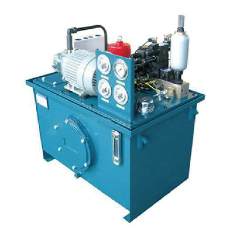 Hydraulic stationThe hydraulic station is the core of the power source of the hydraulic system. It generates pressure oil through the motor-driven oil pump, provides stable power for v...View Product →
On a complete hydraulic station, these details can be written into the specification from the start, along with filtration rating and cooler arrangement. A station assembled as a package is also easier to instrument consistently across several machines on the same site.
 Pressure gaugeCore Advantages As a professional instrument for accurate pressure monitoring, it can capture fluid pressure changes in real time and intuitively display the value, pr...View Product →
Pressure readings belong beside the oil data. A pressure change combined with a stable oil report points at a valve or load issue rather than an oil problem, and that distinction saves a lot of unnecessary oil changes.
A sampling program fails for organizational reasons far more often than technical ones. Six steps keep it running past the second month.
For most industrial power units, a quarterly sample is a reasonable default. Machines running more than 2,000 hours a year justify a shorter interval, and low-cycle machines in damp or outdoor locations justify calendar-based sampling even when running hours are low, because water does not wait for the hour meter to turn.
Start with a baseline 24 to 48 hours after a fill, then sample quarterly for typical industrial duty. Machines running above 2,000 hours per year, or machines exposed to high heat or heavy contamination, warrant a shorter interval. Low-cycle equipment such as lifting columns and roadblock units should be sampled on a calendar schedule regardless of running hours.
Yes, provided the procedure stays identical every time. Consistent sampling point, consistent operating temperature, consistent bottle type and consistent vacuum method matter more than who holds the pump. Many sites train one technician and keep that person responsible for every sample on the site.
Yes. Visible cleanliness only tells you that particles larger than roughly 40 microns are absent. Wear-generating particles in hydraulic systems are typically between 4 and 15 microns, and dissolved water is invisible in the oil at all concentrations below the saturation point. Both are measurable only in a laboratory.
Particle counting combined with water content. Contamination and moisture drive the overwhelming majority of hydraulic component failures, and those two tests together catch both. Add elemental spectroscopy once the machine is critical enough that a pump failure would stop production.
With a stable sampling interval and at least three historical readings, developing wear usually appears several weeks before the machine becomes noticeably degraded. Water ingress and particle contamination can appear within a single sampling cycle, which is why the sampling interval should never be longer than the time you need to react to a bad result.
The value of a hydraulic oil report is not in any single number. It sits in the difference between this reading and the last one, taken from the same port, at the same temperature, from the same machine. Build that consistency into the routine, choose sampling access when the power unit is ordered rather than after it is installed, and the report stops being paperwork and starts being a maintenance schedule written a few weeks ahead of the breakdown.
For teams specifying AC, DC or oil-immersed power units, or building a hydraulic station from the component level up, thinking about oil sampling at the design stage costs almost nothing and pays back on the first avoided failure.
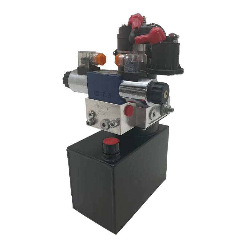
This portable stacker hydraulic power unit is designed for portable stackers and integrates a high-pressure gear pump, a permanent magnet DC motor, a ...
See Details
This hydraulic power unit is specially designed for dump trailers. It is integrated by a high-pressure gear pump, DC carbon brush machine, central val...
See Details
This hydraulic pump station is composed of a series of side inlet and side outlet gear pumps and 4.5 or 5-inch DC motors. It is often used as a hydrau...
See Details
This DC micro power unit combines high-pressure gear pumps, DC motors, center valve blocks, cartridge valves and oil tanks. It is compact and powerful...
See Details
This boarding axle power unit is specially designed for fixed boarding ramps and integrates a high-pressure gear pump, an AC motor center valve block,...
See Details
This oil immersed double actina power unit is designed for efficient, compact and low noise applications, integrating high pressure gear pump, AC oil ...
See Details
This hydraulic power unit is specially designed for the three-dimensional parking garage and is integrated by a high-pressure vanepump, an AC oil imme...
See Details
The V3068 hydraulic valve group is an electric check valve group designed for hydraulic systems. It is mainly used to prevent the backflow of media, e...
See Details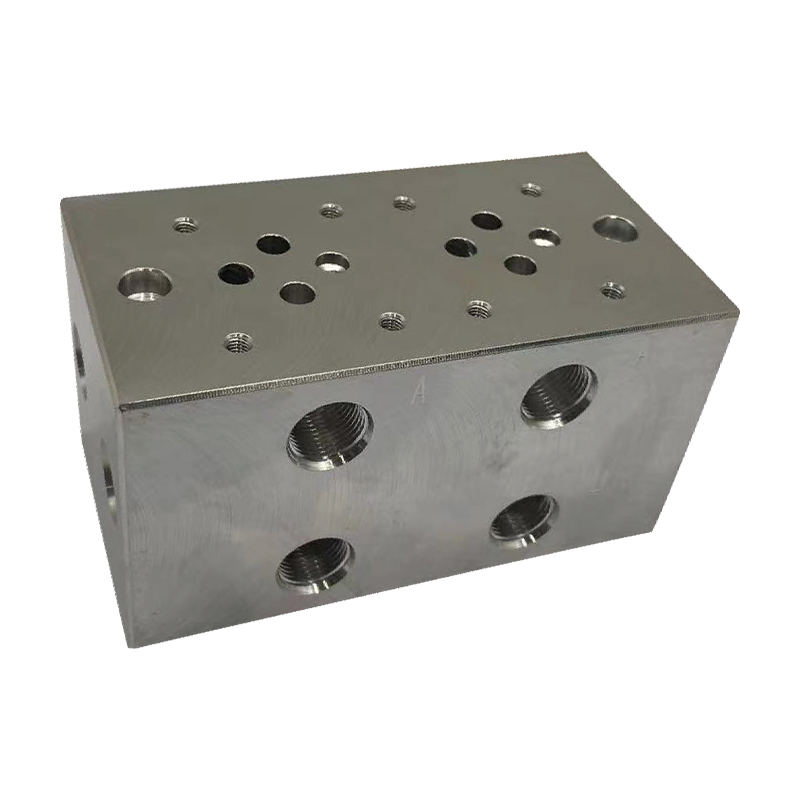
The multi-connection hydraulic integrated valve block is an efficient integrated component of the hydraulic system, including two-connection, three-co...
See Details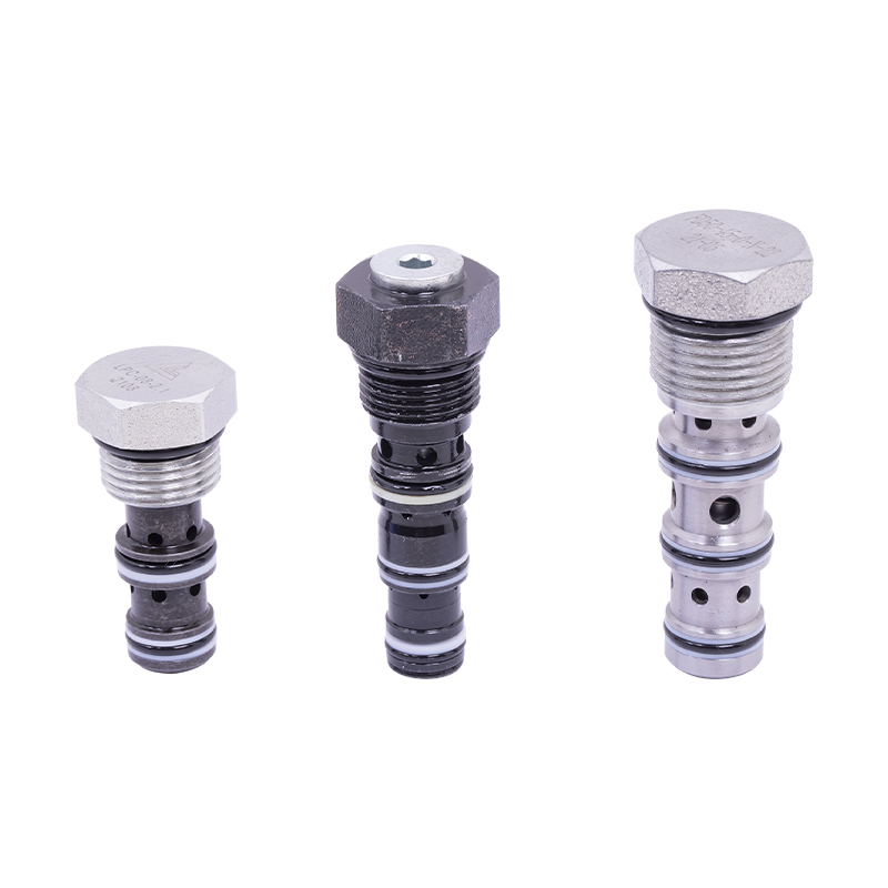
The cartridge hydraulic control check valve controls the on/off and flow direction of the hydraulic oil to start, stop, change direction and lock the ...
See Details
No. 12 Tongji Road, Simen Town, Yuyao City

+86-0574-62130352
+86-18905846028

+86-0574-62130353

Copyright© Ningbo Panic Hydraulic Technology Co., Ltd. All Rights Reserved. China Hydraulic Power Units Manufacturers

