
 English
 中文简体
中文简体 русский
Mobile lifting platform power unit
Cat:DC series hydraulic power unit
This hydraulic power unit is specially designed for a mobile hydraulic lifting table, which is integrated with a high-pressure gear pump. permanent ma...
See DetailsContent
HYDRAULIC POWER UNIT FUNDAMENTALS
An HPU motor converts electrical or mechanical input into the rotational force that drives the pump inside a Hydraulic Power Unit, generating the flow and pressure needed to move cylinders, rotate actuators, or run hydraulic tools. Without the motor, the rest of the Hydraulic Power Unit is just a tank, a manifold, and plumbing. The motor is the single component that turns stored electrical energy into usable mechanical work, and its sizing, speed, and efficiency determine almost every downstream performance number in the system, from cycle time to noise level to electricity cost per hour of operation.
Most industrial Hydraulic Power Units use a three-phase AC induction motor coupled directly to a gear, vane, or piston pump through a flexible coupling or a bell housing. The motor shaft spins the pump shaft at a fixed or variable speed, and that rotation displaces hydraulic fluid out of the reservoir and into the working circuit. In mobile or off-grid applications, the same role is filled by a DC motor running off a battery bank, a hydraulic motor driven by a diesel engine through a power take-off, or in select cases a pneumatic motor where electricity is unavailable or unsafe to use, such as in certain mining or offshore environments.
QUICK REFERENCE
A motor rated at 10 horsepower running a pump with a 2.5 cubic inch displacement at 1800 RPM produces roughly 32.5 gallons per minute of fluid flow. This single relationship between horsepower, displacement, and RPM is the starting point for nearly every HPU motor selection decision.
Before comparing motor types or running sizing calculations, it helps to understand exactly which parts of an HPU motor matter for performance and which parts only matter for installation. An HPU motor is not a generic electric motor bolted onto a hydraulic tank; it is selected and configured around a set of mechanical and electrical interfaces that are specific to hydraulic power transmission.
The motor output shaft carries a keyway or spline that must match the pump's input coupling exactly. A mismatch here is the single most common cause of installation delays on new HPU builds.
NEMA and IEC frame motors use standardized C-face or D-flange mounts so the motor bolts directly to a bell housing without custom brackets, keeping alignment consistent across the build.
Insulation class, typically rated B, F, or H, determines how much heat the windings tolerate before degrading. Class F is the de facto standard for most industrial HPU duty today.
TEFC (Totally Enclosed Fan Cooled) and TENV (Totally Enclosed Non-Ventilated) enclosures protect windings from the oil mist, dust, and washdown spray common around hydraulic equipment.
Selecting the right motor type for a Hydraulic Power Unit depends on duty cycle, available power supply, ambient conditions, and how frequently the unit starts and stops throughout a shift. Below is a comparison of the four motor categories most commonly paired with hydraulic pumps in industrial and mobile equipment, followed by a closer look at where each one earns its place.
| Motor Type | Typical Power Range | Common Use Case | Key Limitation |
|---|---|---|---|
| Three-Phase AC Induction | 1 to 500 HP | Stationary industrial HPUs | Requires three-phase supply |
| Single-Phase AC | 0.5 to 10 HP | Small shop presses, lifts | Lower starting torque |
| DC Motor | 0.5 to 20 HP | Mobile, battery-powered units | Limited continuous duty life |
| Engine-Driven (PTO) | 10 to 1000+ HP | Off-road, agricultural, marine | No utility grid dependency, but needs fuel logistics |
Three-phase motors dominate stationary industrial Hydraulic Power Units because they deliver high starting torque, run efficiently at constant speed, and have decades of proven reliability in factory environments. A typical NEMA-frame three-phase motor in this role runs at 1800 or 3600 RPM, with 1800 RPM being far more common for pump longevity since lower shaft speed reduces wear on pump shaft seals and bearings.
Single-phase motors fill the gap in smaller shops and facilities where three-phase power was never installed. They work well for light-duty presses, lifts, and small test stands under roughly 10 horsepower, but their lower starting torque means they struggle with high-inertia loads or applications that need to start under full pressure.
DC motors are the standard choice for battery-powered Hydraulic Power Units used in scissor lifts, mobile platforms, and electric work trucks. Common voltages are 12V, 24V, and 48V, with higher voltage systems generally delivering more power for less current draw and therefore less heat in the wiring.
When a Hydraulic Power Unit needs to operate far from any electrical grid, an engine-driven PTO arrangement takes over. These setups are common on agricultural equipment, drilling rigs, and marine deck machinery, where diesel or gasoline engines already exist for other purposes and the hydraulic pump simply taps into available shaft power.
Undersizing an HPU motor is one of the most common and most expensive mistakes in hydraulic system design. A motor that cannot deliver enough torque at startup will trip overload protection repeatedly, overheat, and fail well before its rated service life. Oversizing, on the other hand, wastes energy and increases upfront cost without adding any usable performance, and it can also make the motor run less efficiently at partial load.
CORE SIZING FORMULA
HP = (GPM × PSI) / 1714
Where GPM is the required flow rate and PSI is the maximum system pressure. This formula assumes a pump efficiency of roughly 85 to 90 percent, which is typical for new gear and vane pumps operating at normal temperature.
Consider a Hydraulic Power Unit that needs to deliver 15 gallons per minute at 2000 PSI to operate a hydraulic press. Applying the formula: 15 multiplied by 2000 equals 30,000, divided by 1714 equals 17.5 horsepower. In practice, most designers round up to the next standard motor frame size, which would be a 20 HP motor, to account for pump efficiency losses and to leave headroom for pressure spikes during the work cycle.
Duty cycle describes what fraction of an operating hour the motor spends under full load. A press that cycles for 8 seconds and rests for 22 seconds has a duty cycle near 27 percent, which allows a smaller motor than a continuous-duty application like a plastic injection molding clamp that holds pressure for minutes at a time. Motor nameplates list duty rating as S1 for continuous duty or S3 for intermittent duty, and matching this rating to the actual application profile prevents both nuisance overheating and unnecessary oversizing.
A fixed-speed motor running a hydraulic pump at full speed continuously, even when the system only needs partial flow, wastes a substantial amount of energy as heat across the relief valve. Pairing the HPU motor with a Variable Frequency Drive allows the motor speed to track actual system demand instead of running at one constant RPM around the clock.
| Operating Condition | Fixed-Speed Motor | VFD-Controlled Motor |
|---|---|---|
| Idle / Standby | Full power draw maintained | Speed reduced to near zero |
| Partial Load | Excess flow dumped through relief valve | Flow matched directly to demand |
| Startup Inrush | High current spike each start | Soft ramp reduces current spike |
| Noise Level | Constant full-speed noise | Drops with reduced speed |
Field data collected across multiple industrial press and injection molding installations has shown energy savings between 30 and 60 percent after retrofitting fixed-speed HPU motors with variable frequency drives, depending on how much of the duty cycle is spent at partial load versus full load. Applications with long idle or dwell periods, such as plastic injection molding clamp stations, tend to see the largest gains, while applications running near full load continuously see smaller but still meaningful savings.
Pressing and clamping operations, test stands with variable flow requirements, and any HPU that spends significant time idling between cycles are the strongest candidates for a VFD retrofit. Continuous-duty applications running at one steady flow rate around the clock see less benefit, since the motor is already operating near its most efficient point most of the time.
The connection between the motor shaft and the pump shaft is a frequent source of premature failure that has nothing to do with the motor's electrical rating. Misalignment between the motor and pump shaft introduces radial load on bearings that were not designed to carry it, shortening seal and bearing life on both components even when the motor itself is performing exactly as specified.
SAE mounting standards, such as SAE A, B, C, and D flanges, exist specifically so that motors and pumps from different manufacturers can be paired without custom machining. Confirming the SAE flange size and the keyed or splined shaft dimension before purchase avoids a mismatch that would otherwise require a custom adapter, which adds both cost and an extra point of potential misalignment to the drivetrain.
A well-maintained HPU motor in a clean industrial environment can run reliably for 15 to 20 years, while a neglected one in a dirty or overheated environment can fail within 2 to 3 years. The difference almost always comes down to a handful of recurring maintenance habits rather than any single dramatic intervention.
Motor bearings should be inspected for unusual noise, vibration, or heat at regular intervals, with grease intervals following the manufacturer's nameplate or maintenance manual rather than a generic schedule. Over-greasing is just as harmful as under-greasing, since it can cause bearing overheating and seal blowout.
Motor winding temperature is one of the clearest early indicators of trouble before a failure occurs. A sustained winding temperature 10 degrees Celsius above the motor's rated temperature class roughly halves its expected insulation life.
Voltage imbalance across the three phases of more than 1 percent can increase motor heating disproportionately, and sustained imbalance above 5 percent is a common precursor to premature winding failure in industrial HPU motors.
Cooling fins, vents, and the area around the motor should stay free of hydraulic oil residue, metal fines, and dust, since contamination buildup restricts airflow and is one of the leading causes of slow, hard-to-diagnose overheating.
Quarterly Maintenance Checklist
Most reported HPU motor issues trace back to one of three root causes: electrical supply problems, mechanical coupling problems, or hydraulic system backpressure being mistaken for a motor fault. Separating these early prevents replacing a perfectly good motor when the actual problem is elsewhere in the circuit.
| Symptom | Likely Cause | First Check |
|---|---|---|
| Motor hums but does not turn | Single-phase loss or seized pump | Check all three phase voltages |
| Frequent overload trips | Undersized motor or high system pressure | Verify relief valve setting against motor rating |
| Excessive vibration | Coupling misalignment or worn bearings | Inspect coupling alignment first |
| Overheating during normal duty | Blocked ventilation or low voltage | Clean vents and measure supply voltage |
| Slow or weak cylinder movement | Worn pump rather than motor issue | Measure actual flow output against rated GPM |
A simple amperage check goes a long way toward separating a true motor problem from a hydraulic system problem. If the motor draws normal current but the system underperforms, the issue is almost always downstream in the pump, valves, or actuators. If the motor draws excessive current relative to its nameplate rating, the load on the motor itself, whether from the pump or from a mechanical binding issue, is the more likely culprit.
Motor size depends on required flow rate and maximum system pressure, calculated using the formula HP equals GPM times PSI divided by 1714. A press needing 15 GPM at 2000 PSI requires approximately 17.5 HP, typically rounded up to a 20 HP motor frame to leave margin for pressure spikes.
Yes, single-phase motors can drive smaller Hydraulic Power Units up to roughly 10 HP, but they generally have lower starting torque than three-phase motors of the same rating, which matters for applications with high startup load such as presses that start under pressure.
A properly sized and maintained HPU motor in a clean environment commonly lasts 15 to 20 years of service, while motors exposed to heat, dust, voltage imbalance, or chronic misalignment often fail within 2 to 3 years.
The most common causes are blocked cooling vents restricting airflow, supply voltage running below the nameplate rating, or the pump demanding more torque than the motor is rated to deliver continuously due to oversized relief valve settings.
Yes, field results across industrial installations show energy savings between 30 and 60 percent after adding variable frequency drive control, with the largest gains seen in applications that have long idle or partial-load periods between work cycles.
Motor horsepower describes how much rotational power the motor can deliver, while pump displacement describes how much fluid volume the pump moves per revolution. Together at a given RPM, these two values determine the system's actual flow rate and pressure capability.
Class F insulation is the standard choice for most industrial HPU motors today, offering a higher temperature tolerance than older Class B designs while remaining widely available across motor brands and frame sizes.
Alignment should be verified at installation, rechecked after the first 100 hours of operation as mounting hardware settles, and then inspected during routine quarterly maintenance, or sooner if vibration or noise increases noticeably.

This hydraulic power unit is specially designed for a mobile hydraulic lifting table, which is integrated with a high-pressure gear pump. permanent ma...
See Details
This DC bidirectional pump power unit adopts an integrated design of multiple components such as a bidirectional gear pump, a permanent magnet DC moto...
See Details
This DC single acting power unit is designed for mobile hydraulic lifting platforms. It provides an efficient and reliable hydraulic power solution th...
See Details
This hydraulic power unit is designed specifically for CNC machine tool cutting cylinders and can provide precise power and control, consisting of a h...
See Details
This hydraulic power unit is specially designed for a double-acting oil cylinder system, which is integrated by a high-pressure gear pump, an AC motor...
See Details
The hydraulic power unit is specially designed for the integrated hydraulic lifting column, which is integrated by a two-way gear pump, an AC oil imme...
See Details
This hydraulic power unit is specially designed for an anti-terrorism hydraulic roadblock machine. It is integrated by a high-pressure gear pump, an A...
See Details
This hydraulic power unit is designed to meet extreme security needs, especially for critical occasions where large vehicles such as heavy trucks and ...
See Details
The hydraulic solenoid valve is a key component in the hydraulic system that controls the opening and closing or reversing of the hydraulic oil passag...
See Details
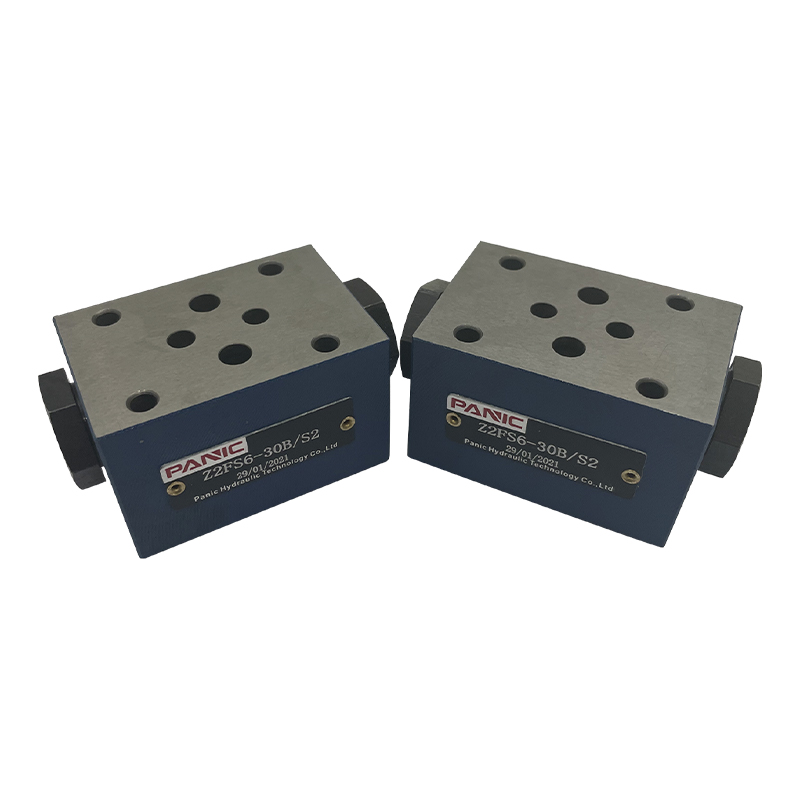
The pressure compensation valve is a key component in the hydraulic system to maintain flow stability. It can automatically adjust the valve opening w...
See Details
No. 12 Tongji Road, Simen Town, Yuyao City

+86-0574-62130352
+86-18905846028

+86-0574-62130353

Copyright© Ningbo Panic Hydraulic Technology Co., Ltd. All Rights Reserved. China Hydraulic Power Units Manufacturers
